
Oscilloscope Tool Tutorial
Digital oscilloscopes are very powerful and useful tools in diagnosing electrical signals. When you have a signal changing very fast the oscilloscope can view that signal and take measurements of that signal. This section will go over the basics of using a digital oscilloscope. The Oscilloscope Manual is a great resource for getting into the more advanced features once you are comfortable using the scope.
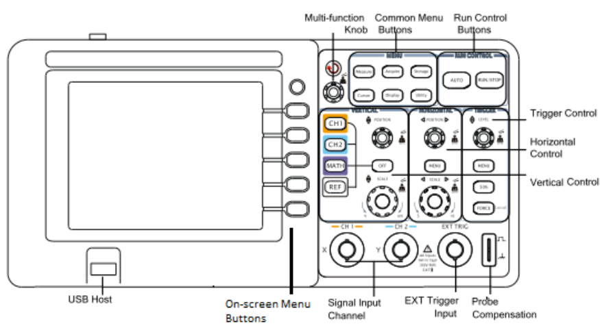
Controls
The main controls for the digital oscilloscope are:
- Power on/off
- Multi-function knob
- Common Menu Buttons
- Measure
- Acquire
- Storage
- Cursor
- Display
- Utility
- Measure
- Run Control Buttons
- Auto
- Run/Stop
- Auto
- Vertical Control Area
- CH1
- CH2
- MATH
- REF
- Position Knob
- Scale Knob
- CH1
- Horizontal Control Area
- Position Knob
- Scale Knob
- Position Knob
- Trigger Control Area
- Level Knob
- Menu Button
- 50% Button
- Force Button
- Level Knob
Probes
To connect what you are measuring to the oscilloscope you need probes. These probes have a selection of 10x on them, which means that when the 10x is selected the voltage input to the oscilloscope will be 10 times smaller. This is useful if you need to measure higher voltages.
For any measurements under 30V you will not need the 10x selection, the oscilloscope can go to 40V but to be safe only go to 30V before using the 10x selection.
- Check that the function generator is set to less than 30V (since it goes to 20V that should not be hard) and connect the function generator output CH1 to the oscilloscope input CH1.
Time Divisions
From this point on, we use the function generator to generate signals for us to observe on the oscilloscope. See the Function Generator Tool Tutorial for details on how to use the function generator.
- Turn on the oscilloscope and check that CH1 button is lit up.
- Set the function generator to a sine wave at 5V and 100Hz. The screen should be displaying a signal.
- Change the function generator to 10kHz.
- The signal should now be hard to see.
- Use the Scale Knob in the Horizontal Control area and turn the knob so that the waveform stretches out on the screen.
The signal is still the same; you are just zooming in by changing the time divisions. The current time division is displayed at the bottom of the screen next to the word Time. This value is the horizontal size of one box in the grid on the display. The horizontal scale knob controls both CH1 and CH2 signals at the same time.
Voltage Divisions
- Decrease the voltage on the function generator to 1V.
- Use the Scale Knob in the Vertical Control area to increase the displayed size of the waveform.
The vertical scale for each of the channels is separate so if the scale is not changing make sure you have CH1 selected. The current value of the vertical scale is displayed at the bottom of the screen where it says CH1 or CH2 and then a value in volts. - Decrease voltage on function generator and change the voltage divisions so that the waveform is more visible.
Triggering
On the display the signal looks like a stationary wave, this is due to the triggering. Triggering determines where on the waveform the oscilloscope considers the starting point.
- Turn the Level Knob and you will see a horizontal line, that is the trigger level and when the waveform crosses this line the oscilloscope uses this as fixed point on the display.
- Adjust the Level Knob so that the trigger level is above the waveform, the waveform will now starting moving on the display. This is due to the oscilloscope no longer triggering off of the waveform and triggering based on a timeout.
- Use the 50% button in the Trigger Control Area to return to triggering off of the waveform.
- Turn off the output on the function generator and disconnect the function generator from the oscilloscope.
- Attach the piezobuzzer to the oscilloscope, tap on it and you should see something flash by on the display.
What flashed by was the signal from the piezobuzzer. Since it is just a short pulse you will need to set up the oscilloscope to freeze and hold the image of that pulse. - Press the Menu button in the Trigger Control Area.
- On the onscreen menu, select the Sweep and change it to single. In the Run Control Area the Run/Stop button should now be green.
- Tap the piezobuzzer again - it should display and hold the signal and the Run/Stop button will turn red.
- Tap the piezobuzzer again and nothing will happen, but if you press the Run/Stop button again it will go green and it will be ready to trigger again.
- In the Sweep option, change it to the normal mode - it will trigger on every signal that meets the threshold but will not timeout trigger as it does in auto mode.
Measuring Amplitude
One of the main uses of the digital oscilloscope is to get accurate measurements of signal. This digital oscilloscope has a variety of amplitude measurement options. Appendix A shows the types of amplitude measurements that the Rigol DG1052 can perform, we will be using the voltage peak to peak (Vpp) for this example.
- Reconnect the function generator to the oscilloscope, turn on the output and set the oscilloscope to auto trigger.
- In the Common Menu Buttons area, press the Measure button.
- In the on-screen menu, check that the source is CH1 and use the Voltage option to select Vpp.
The measurement of the signal should now display on the screen. - Change the function generator voltage and see how it tracks the changes.
- Turn off the function generator and disconnect it from the oscilloscope.
- Set the oscilloscope to a single trigger, connect the piezobuzzer to the input and give the piezobuzzer a good smack.
This should give you a nice waveform to measure. - If the Vpp measurement is no longer on the screen, repeat the steps above to bring up the measurement.
This shows how you can measure captured waveforms the same way as repeating waveforms.
Measuring Time
Time values are the other important measurements that can also be measured on the digital oscilloscope. Appendix B shows the types of time measurements that the Rigol DG1052 can perform; we will be using the frequency measurement
for this example.
- Reconnect the function generator to the oscilloscope, turn on the output and set the oscilloscope to auto trigger.
- In the Common Menu Buttons area, press the Measure button.
- In the on-screen menu, check that the source is CH1 and use the Time option to select Freq.
- The measurement of the signal should now display on the screen.
- Change the function generator frequency and see how it tracks the changes. Then turn off the function generator and disconnect it from the oscilloscope.
- Set the oscilloscope to a normal trigger, connect the piezobuzzer to the input and sing to your piezobuzzer to make up for smacking it!
- When you get a good signal on the display, press the Run/Stop button to freeze the signal.
- If the frequency measurement is no longer on the screen repeat the steps above to bring up the measurement.
Now you can measure how much in tune (or out of tune) your singing is!
Cleanup
- After you are done using a power supply or function generator, always turn down the voltage and turn off the output before turning off the main power.
- Gently wind the probes and wires up so there are no tight bends in the wire that could break the wire over time. This is especially important with the oscilloscope probes to keep them in proper working order.
- Clean up the table and floor around where you worked.
No Comments