
Tool Tutorial
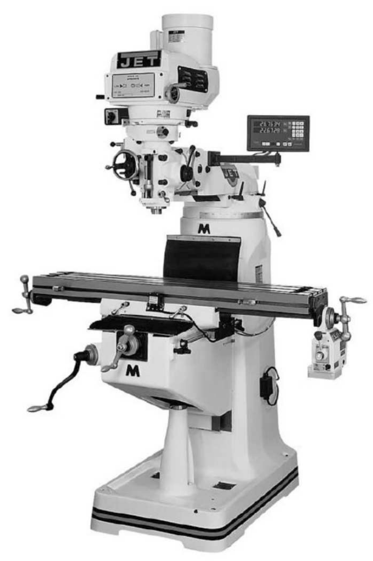
JET Vertical Mill
Loose clothing should not be worn around the mill. ABSOLUTELY NO GLOVES may be worn while operating the mill: this includes latex, nitrile, vinyl, and similar gloves. Any jewelry on the hands or wrists must taken off while using the mill. Long sleeves should be rolled up and secured past the elbows. Long hair must be pulled back and secured. Watch out for loose clothing or loose jewelry
Never leave the wrench on the draw bar for any length of time - this becomes a projectile hazard.
Never lean on the machine. Always keep your weight back.
Watch out for chips. The mill may produce long ribbon-like metal shavings that can cut you or pull you into the machine. Consult a shop tech if you are continuously getting long hazardous chips.
The mill, as well as the metal lathe, can be thought of as one of the two basic machines of a machine shop. From these two machines nearly infinite number of parts can be made. While the mill is used primarily for making parts with flat sides and angles, it can be used for much more. Mills can come with a variety of attachments and tooling to do many things, from boring large holes to making
gears.
A milling machine is used to machine surfaces so they are flat and have precise dimensions, to cut slots and voids, and to even drill holes to precise depths. When using a milling machine for general operations, you clamp your work piece securely to the table with the machinist’s vise or special clamps and as your work piece is moved by the table relative to the end mill which is being spun by the milling machine’s spindle motor.
Equipment Controls
The primary controls you will use on the mill:
- Speed adjustment mechanism
- Table X axis wheel (left to right)
- Table Y axis wheel (backward and forward)
- Table Z axis crank or knee crank (up and down)
- Power control (turns the mill on and off)
- Spindle (quill) lever (lowers the spindle and quill like a drill press)
- DRO (digital read-out) zeroing buttons
Specifications
- Table size: 9" x 49"
- Longitudinal table travel, maximum: 34"
- Number of T-slots: 3
- T-slot size (W x D): 5/8" x 3/4"
- T-slot centers: 2-1/2"
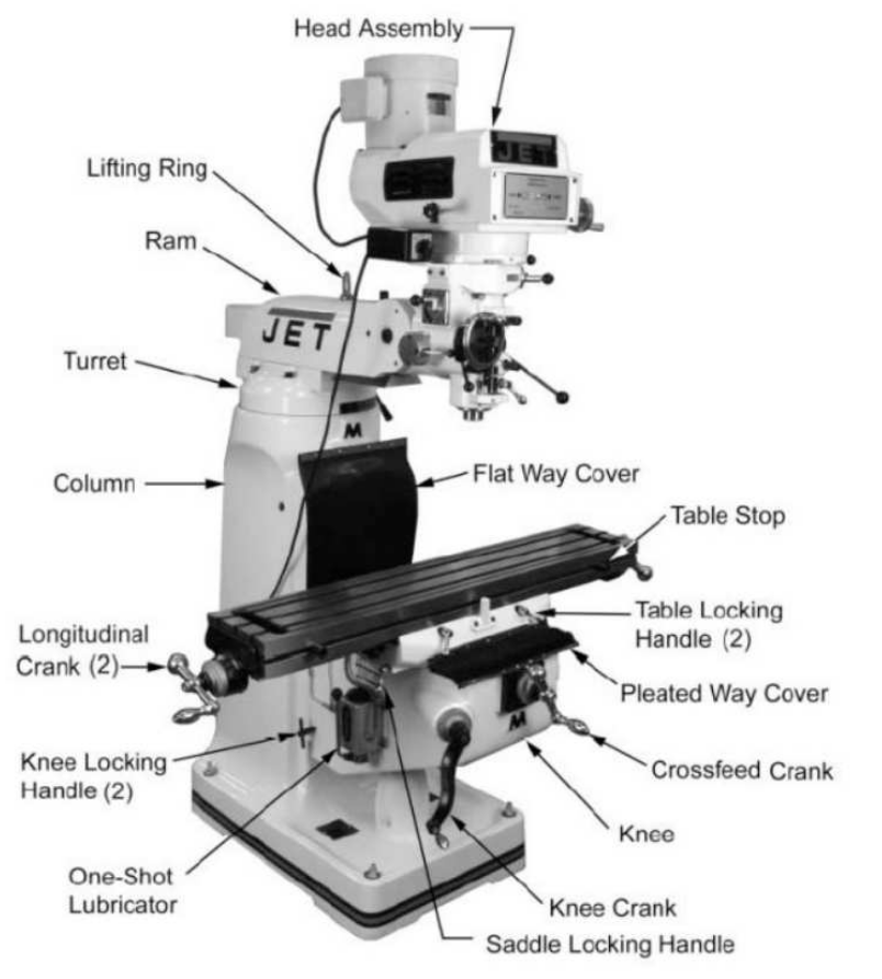
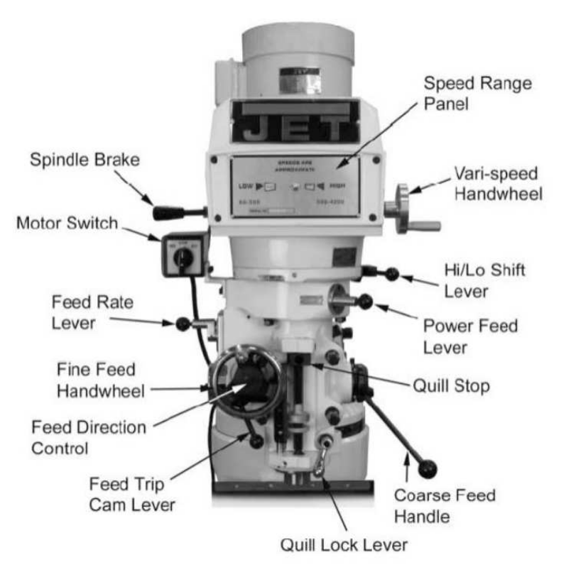
Head Assembly
The head assembly of the mill contains several controls; most important to know are the speed adjustment and the hand quill feed. Many mills adjust their RPM using stepped pulleys and a high and low gear. Some may also have a high and low motor speed. Some mill heads do not have stepped pulleys but instead have a variable speed adjustment. Stepped pulleys are changed when the machine is off; variable speed heads have their speed adjusted while the machine is on. All mills have a high and low gear. Gearing is
changed only when the machine is off and are done per machine instruction.
When you switch gears, the spindle of the mill will turn in the opposite direction it did before. For this and several other reasons, the motors in mills can be run in both directions. Some mills say Forward and Reverse while others say nothing. Always make sure the cutter is turning the right way when you turn on the machine.
Further down the head is a lever that resembles the lever of a drill press. This is the quill hand feed, or coarse feed handle, and it serves the same purpose on the drill press. This allows you to bring the quill up and down. Notice that a metal ring moves up and down when this is done. This is the quill stop and can be used to set the height of the quill. A little further down is a small lever, the
quill lock, which locks the quill in whatever position you have it. The quill should always be lock engaged (locked) when you are milling.
Table
The mill has a large T-slot table upon which all work is attached. It is common to hold small work to a precision vise mounted on top of the table. Pieces clamped to the table are done using T-nuts and hold-down clamps available in the machine shop. A sacrificial piece should always be placed under the work piece to protect the table.
Hand Wheels
The mill table has freedom to move in two axes, the X and the Y, by turning different hand wheels. On each hand wheel is a dial that allows you to accurately measure the distance the table has moved; keep in mind, however, that there is backlash that you must account for. For each axis there is a lock that locks the table.
Always lock all of the axes you are not using for milling.
Knee
The knee is the large mass of cast iron that supports the table. It is moved up and down (move the Z axis) with the knee crank. The lock for the knee is usually located right beside the knee crank but may be located around the side of the column. For accuracy and stability, always lock the knee as well as crank up to your final position.
Basic Operation
Check Mill
Before getting started, check the mill to notice any differences since the last time you used it, and to see whether there is anything you might be unfamiliar with. Ensure the power quill feed is disengaged by unlocking the quill and testing to make sure it moves freely. Also be sure the vise is clamped and that the table and knee move smoothly and freely.
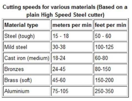
Determine RPM
Before performing any operation, you should determine the correct RPM (revolutions per minute) to use for the operation. The RPM is determined by three variables: the work material, tooling material, and diameter of the tool. For every work-material/tool-material combination, there is a different cutting speed in feet/minute. Cutting speeds for some material can be found on charts in the shop, and more extensive charts are in Machinery's Handbook. From this linear speed, the RPM is determined by the following formula:
RPM= (CS * 4) / D
where
- CS = cut speed
- D = diameter of stock (lathe) or diameter of cutting tool (mill), in inches
- RPM = speed of the rotating part or tool, in revolutions per minute
The cutting speed is given as a set of constants that are available from the material manufacturer or supplier. The most common materials are available in reference books or charts but will always be subject to adjustment depending on the cutting conditions.
Feed Rate
Feed rate is the speed the tool moves relative to a fixed, stationary part. It is the autofeed rate when autofeed is used and is usually measured in inches per minute on a mill, or inches per revolution on a lathe. When just learning the mill, you should try to feed by hand and so will be using your senses to determine the correct speed. In order not to overtax the machine, you will feed the tool through the work so that you do not feel any undue resistance to your movement but so that you also cut efficiently.
Load the End Mill
End mills are held in the mill by an R8 collet. An end mill has two diameters: the shank diameter and the cutting edge diameter. Often these can be the same. To load the end mill, select a collet that matches the shank diameter of your end mill. Insert the end mill so that the flutes are as close to the end of the collet as possible without being inside. Load the end mill and collet into the spindle by
matching the key way. While holding the collet up in the spindle, turn the draw bar and tighten until finger tight. Next, tighten the draw bar with the wrench while holding the spindle brake. Make sure to put the wrench back. It is important to tighten the draw bar so that it is more than snug -- but be careful not to over tighten. Aim for tight and secure, rather than as tight as possible (monkey tight, not gorilla tight).
Put Work in Vise
When securing the work in the vise, take care that at least some to the work is held by the center of the vise. Also be sure there is sufficient clearance between the top of the vise and the work. You may need to use parallels to achieve this height. Tighten the vise more than snug -- the same way you would tighten the drawbar.
Turn Mill On
Check the mill to ensure nothing is in the way or could get caught in the spinning mill. Double-check which way the end mill must spin in order to cut. Turn the end mill on and make sure that it is spinning the correct way. You may have to turn the machine off and let it spin down to check.
Zero Your Part
There are many different ways to zero your part. A quick and easy way is to slowly bring the end mill in contact with the work until it scrapes off just a tiny bit of material. Zero the dial or the DRO and back off slightly.
Mill the Surface
Milling removes material from the surface of your workpiece with the rotary cutting tool. First choose the depth of cut. To determine this, start with a very light cut and take progressively more until you find a balance between depth and feed speed. Do not cut deeper than half the diameter of the cutter in a single pass nor more than twice the diameter of the cutter overall on any slot or step.
Once you've chosen the depth of cut, you will start off the piece with the end mill engaged less than or equal to 50% of the diameter. Start at a side that ensures that when you feed the cutter through the work you will not be climb cutting. After you are set up, lock the axis that you are not feeding in, and then begin slowly and evenly to feed the cutter through the work till it is out. It is usually most efficient to make a spiral cut or to cut coming back on the other side of the piece.
Mill a Channel
Milling a channel is very similar to milling a surface, in that you will be using the rotary cutter to remove material from your workpiece, but instead of removing material only on the surface, the cutter is engaged 100% of its diameter and creates a channel.
Cleanup
- Remove all tooling and return it to the appropriate location.
- Put the rolling cart out of the way.
- If you have broken or damaged any tooling, please do not return it to the tooling storage. Instead, speak to a shop tech or take it to the front desk so it can be evaluated and replaced, if necessary.
- Clean up all of your chips and any other chips in the general area. Use a broom or vacuum cleaner, as needed.
- Wipe up any coolant or lubricant and leave the machine clean and dry.
- If you have used a special setup or have changed something so that it is no longer in its expected position, please reset it or find a shop tech to show you how to reset it (e.g., let us know if the machine is now out of tram).
No Comments