
Tool Tutorial
Edwards 55 Ton Ironworker
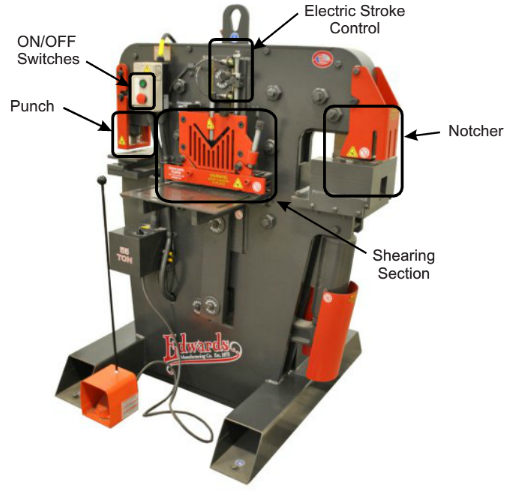
The ironworker’s main strength is its versatility. It can shear, punch, and notch a variety of
different materials. The ironworker consists of three primary sections: The shear,
the notcher and the punch.
Shear
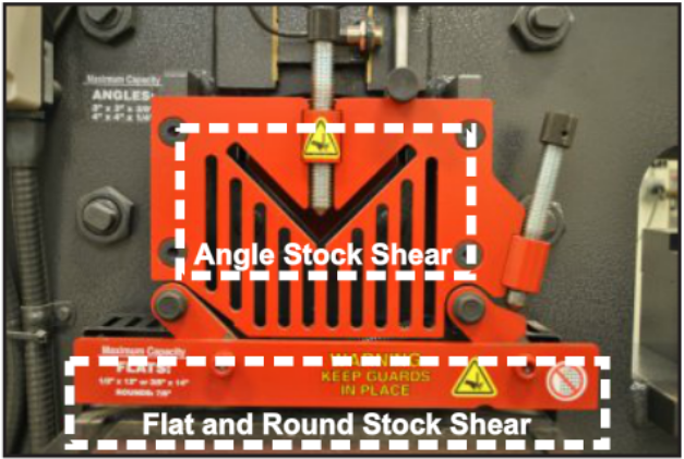
This section of the machine can shear angle, round stock, and flat stock of varying thicknesses. The
shear section of the ironworker consists of a dedicated angle shear and a dedicated flat and
round stock shear.
Angle Iron Shear
The angle iron section of the machine consists of an angled slot through which material is fed to be sheared. A “V” shaped blade shears the material when the pedal is depressed. The shear can cut thick angle iron which is very inefficient and harder to hold safely on the cold saw and horizontal bandsaw. When cutting very large pieces be sure to have someone behind the machine catching the cut pieces. This will help prevent damage to the machine and others.
Flat and Round Stock Shear
The flat stock section of the shear allows the user to shear thick plate and round stock metals very quickly. Pieces that cannot be appropriately held on the bandsaw and can fit within the size requirements should be sheared on the ironworker.
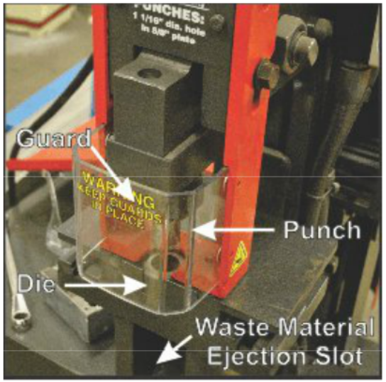
Punch
The punch will punch holes in very heavy gauge material. This tool works very well with all types of plate materials. It will punch through thick plate steel in a couple of seconds where the drill press would take minutes. The hole sizes are limited to the punch and die sets that are available. Punch and die sets are available in different shapes such as round, square, rectangle, hex, oblong. Protohaven has common sizes in square and round. If a specific die is needed, it can be purchased from the manufacturer. If a hole is needed that is in between available hole sizes, a hole can be punched slightly smaller than the desired hole size. This hole can then quickly be enlarged on the drill press. Ask a shop tech for assistance if you need help changing dies.
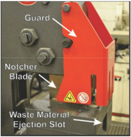
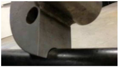
Notcher
The notcher is used to cut notches out of material for a variety of purposes. When a piece needs to fit within a slot, a tongue can be created by removing a square chunk of material from both sides. Any angle can be cut on the notcher by moving the material to the desired angle. One of the most useful applications for the notcher is for removing sections of one leg of angle stock for assembly purposes. This operation would require multiple steps on other machines but can be done in one quick step on the ironworker.
Safety Features & Precautions
Machine Guards
Each section of the ironworker has a guard to prevent injury to the user during operation. It is imperative that guards remain seated slightly above the material you are working with. This prevents injury and damage to the machine and your work.
Shear
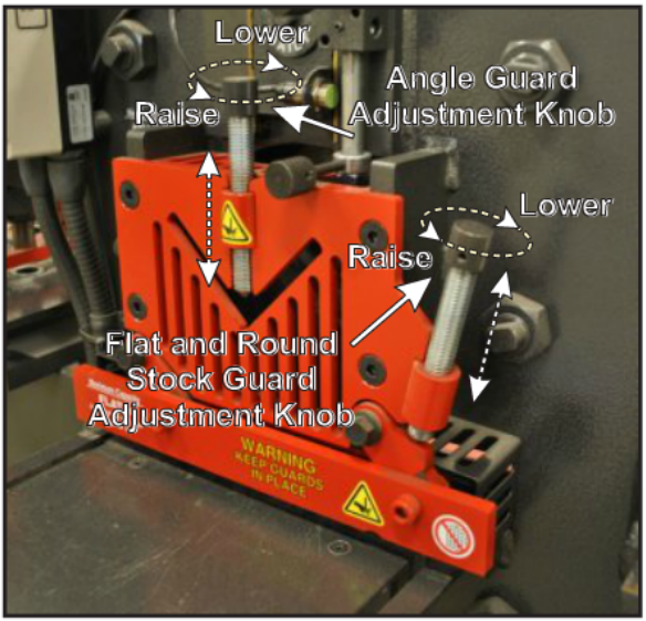
There are two shear guards. There is one guard for securing angle stock and another for securing flat and round stock. When working on this machine make sure the guard is lowered to the height of your material. It needs to be almost touching your material. The guard should be no further away from your material than 1/32” - 1/16” for flat and round stock and should make contact with angle stock.
The guards on the shear are raised and lowered by turning a screw. The angle stock guard consists of a screw with a tapered end to secure the material. Secure angle stock tightly with this screw. The flat and round stock guard consists of a bar that is lowered by a screw. It is not spring loaded so it will need to be moved up by hand when it needs to be raised. Simply turning the screw counter clockwise will not raise the flat and round stock guard.
The material ejection ports on the back of the shear are covered to prevent access to the blades while the machine is in operation. When cutting large or heavy material make sure you have someone catching the material as it is cut. This will prevent damage to the machine and others.
Punch
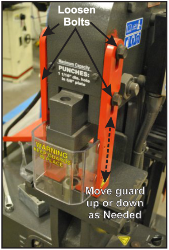
The guard on the punch should always be seated very close to the material while the machine is in operation. The guard should be located 1/32"-1/16” above the material being punched. Extra space should be made for the material as it will slightly deform after being punched and will then be impossible to remove from the machine without moving the guard. The guard is moved by loosen-
ing the bolts on either side, then lifting it up or down as needed and then re-tightening the bolts.
Important: Align the punch and die before using them to punch holes. Carefully lower the punch into the die and, if needed, align them The table can be adjusted by loosening the 3/4" bolts on the underside. 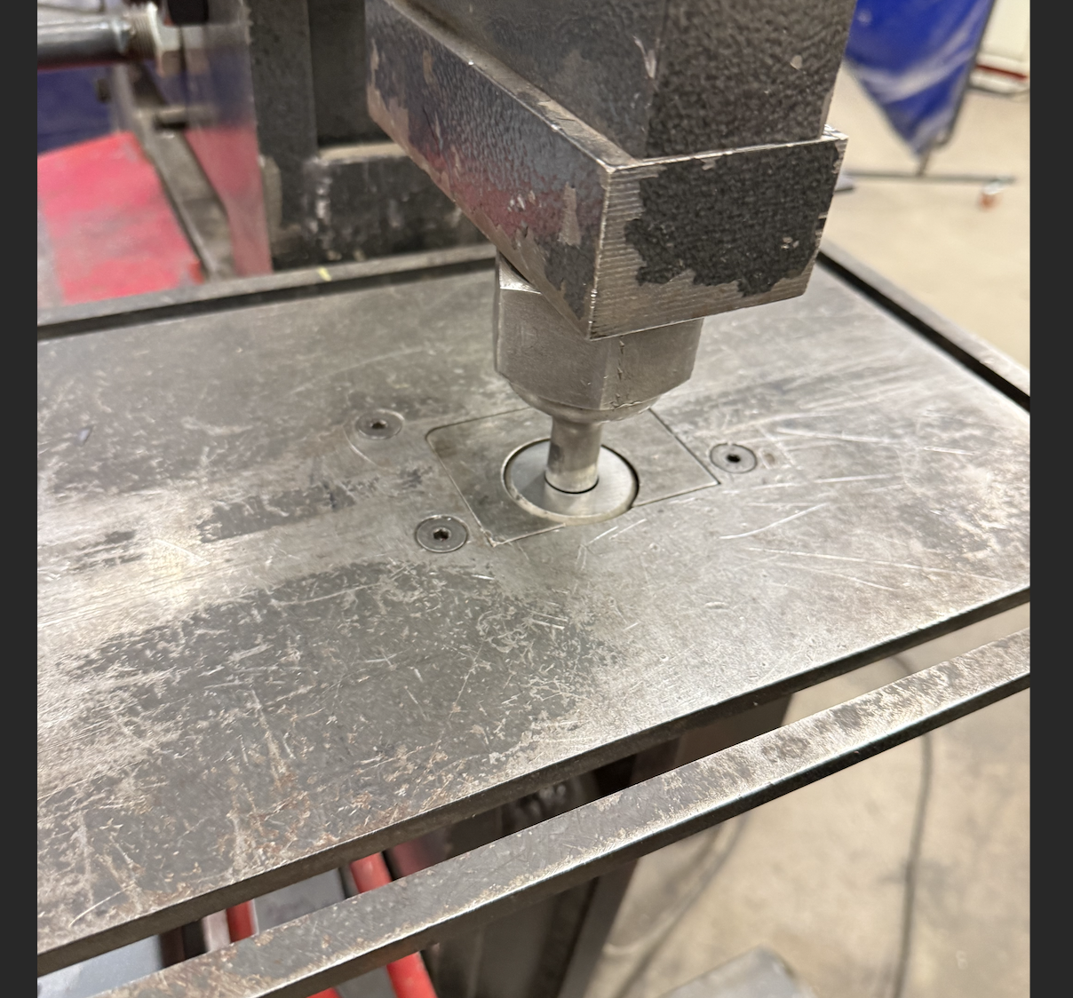
Notcher
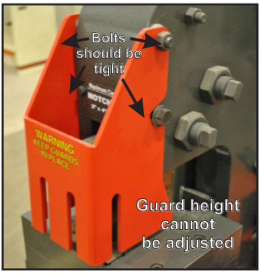
The notcher guard helps prevent injury from the tool. The notcher should always be operated with the guard down and lowered
to 1/32” - 1/16” above the material. The guard swings out towards the operator and is tightened in place with two bolts. Make sure the bolts are tightened before operating the machine. The notcher guard is set to a fixed height for the maximum material thickness. The guard placement should not need to be adjusted. The slots in the guard are designed for usage with angle stock and allow clearance for the vertical leg of the material.
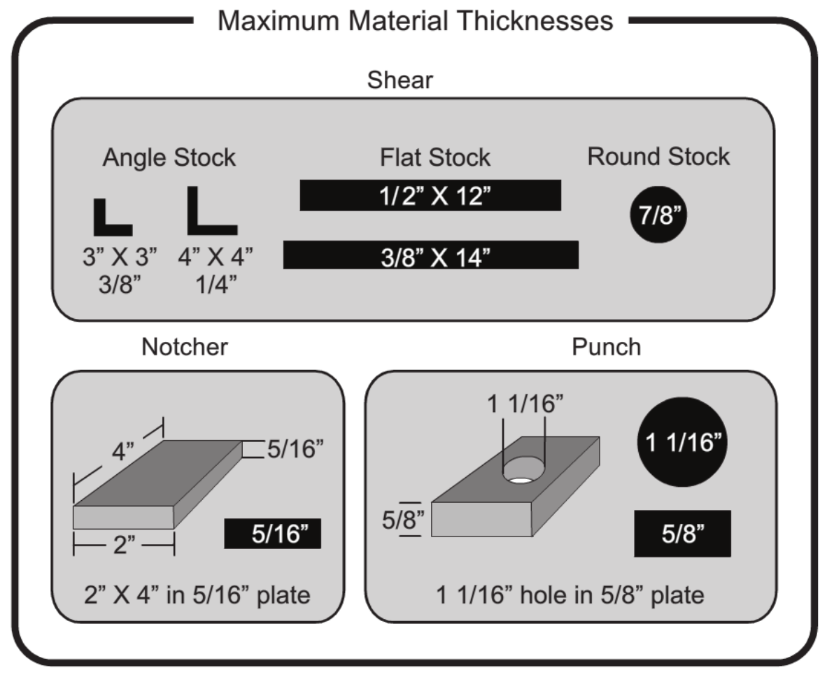
Maximum Material Capacity
The ironworker is capable of shearing, punching and notching very thick plate metals but it is very important that the maximum capacities of the machine are followed. Damage to the machine will be minimized by following these capacities. The capacity of each section of the machine are clearly labeled. Please refer to the labels on the machine or in the following chart for the maximum material capacities of the ironworker. Tool steels are not to be used on this machine. Stainless steel can be used but not at the maximum thickness capacities of the machine. Always check with a shop tech anytime you want to use the machine for materials harder than mild steel.
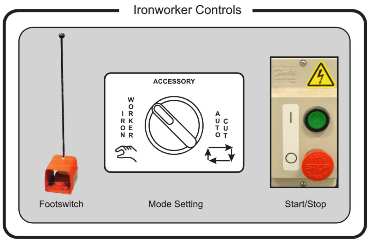
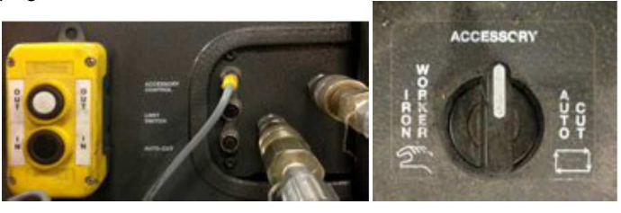
Controls
The ironworker controls are very basic. There is a start and stop button that turns the machine on and off. A footswitch actuates the movement of the machine. When the footswitch is depressed and held, the shear, punch and notcher run through one full cycle of movement. All three tools move simultaneously. Three different modes are available that can be selected when the machine is not running. The available modes are ironworker, accessory, and autocut.
Ironworker Mode
When the ironworker mode is selected the shear, punch, and notcher are available for use. This is the primary mode for the ironworker.
Accessory Mode
This mode is selected when the ironworker’s hydraulic tube and pipe bender attachment is used. The ironworker’s power is fed to the hydraulic bender and none of the ironworker’s tools (shear, punch, notcher) will move when the bender is in use.
Auto Cut Mode
The auto cut mode is used when an attachable auto cut device is used. The auto cut device plugs into the back of the machine and is used for shearing operations. It consists of a movable stop with a trigger. When the trigger is hit the ironworker will engage and cut the material at the desired length. This device is not currently available.
Basic Operation
Shear
The distance from the angle stock guard front face to the blade is 4 13/16” and the distance from the flat and round stock guard front face to the blade is 5 7/16”. Make sure to account for this distance when cutting your material by adding it to the length you desire to cut and then align your mark to the front face of the guard.
Cutting Flat or Round Stock
- Mark material with sharpie or scribe at desired cut length.
- Place material on bed.
- Move material to desired location for cut.
- Set guard to 1/32"-1/16” above material by turning the adjustment knob.
- Turn machine ON by pressing the green button.
- When hands are free of any pinch points and NOT located under your material depress the footswitch.
- Release the foot pedal when the machine has completed one full cycle and the blades have returned to their starting position.
- Turn the machine OFF by pressing the red button when all cutting is complete.
- Dispose of any scrap material in the metal scrap bin.
Cutting Angle Stock
- Mark material with sharpie or scribe at desired cut length.
- Place material into angle stock slot.
- Move material to desired location for cut.
- Turning the adjustment knob until the tapered screw has made contact with the material.
- Turn machine ON by pressing the green button.
- When hands are free of any pinch points and NOT located under your material depress the footswitch.
- Release the foot pedal when the machine has completed one full cycle and the blades have returned to their starting position.
- Turn the machine OFF by pressing the red button when all cutting is complete.
- Dispose of any scrap material in the metal scrap bin
Punch
- Use center punch to mark desired location of hole.
- Place material on bed.
- Move material to desired location for cut.
- Set guard to 1/32°-1/16” above material by loosening the guard bolts, moving the guard and then re-tightening the guard bolts.
- Turn machine ON by pressing the green button.
- When hands are free of any pinch points and NOT located under your material depress the footswitch.
- Release the foot pedal when the machine has completed one full cycle and the blades have returned to their starting position.
- Turn the machine OFF by pressing the red button when all cutting is complete.
- Dispose of any scrap material in the metal scrap bin.
The punch can be very loud and startling to other members when in operation. Verbally notify other members when performing punching operations with large diameters.
Notcher
- Draw desired cut on material with sharpie or scribe.
- Place material onto the bed.
- Set guard to 1/32”-1/16” above material by loosening the guard bolts, pivoting the guard to correct location and then re-tightening the guard bolts.
- Turn machine ON by pressing the green button.
- When hands are free of any pinch points and NOT located under your material depress the footswitch.
- Release the foot pedal when the machine has completed one full cycle and the blades have returned to their starting position.
- Turn the machine OFF by pressing the red button when all cutting is complete.
- Dispose of any scrap material in the metal scrap bin.
Useful Links
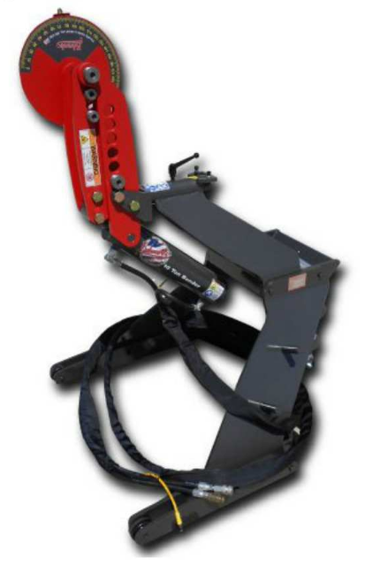
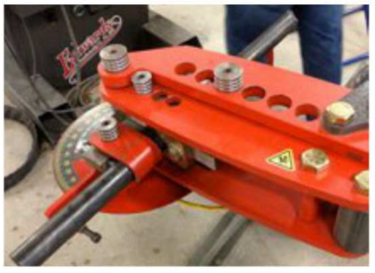
Edwards 10-Ton Tube and Pipe Bender
The tube and pipe bender is a quick-connect hydraulic tool that expands the capabilities of the Ironworker. It is designed for medium to heavy duty material, bends up to 2” (1.D.) Schedule 40 pipe, 2.5” (O.D.) tube and 2” square tube quickly and accurately.
Pipe Bending
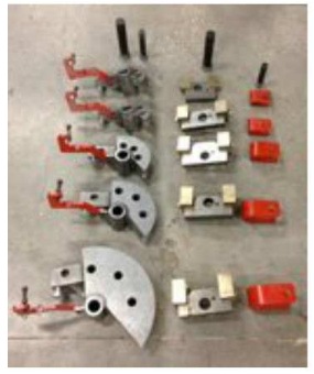
To bend pipe on the pipe bender you need to have the proper dies for the size pipe you want to bend. We currently have pipe dies for you to choose from.
Connecting the Pipe Bender
Once you have rolled the pipe bender near the Ironworker you have to connect it to the Ironworker. There are three cables bundled together and then the remote. The male and female hydraulic connections go to their opposites and the remote cable goes in the top plug labeled accessory control. The yellow cable operates the limit switch you can set where you want your bend to stop, it plugs into the plug labeled limit switch.
Setting up the Pipe Bender
After connecting the pipe bender to the Ironworker, it’s time to set up your bend. First, you need to find the right size die for your pipe.
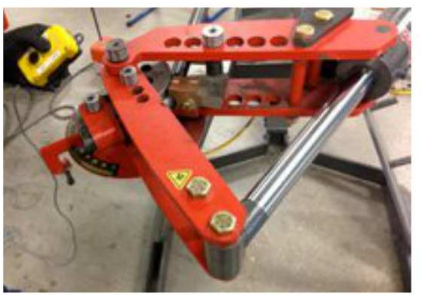
Second, you need to decide if you are bending horizontally or vertically. There needs to be enough clearance around the bender for your material to move during the bend without hitting anything.
NOTE: If you have a long pipe you are bending there is more room for the end of the pipe if you bend it vertically towards the sky. Smaller length pipe that will not contact with the things sitting around the bender can be done horizontally.
Once you have chosen the correct size die for your pipe, start by putting the die on the bender with the large pin going through the arms of the bender and the center of your die.
Next, take your backstop that matches the die and install it on the non-moving arm of the bender with another pin. Make sure that the screw is towards the bottom of the bender.
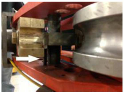
Now you can slide your pipe into the bender between the die and backstop. The collar that holds the pipe goes on next using the short pin.
NOTE: If you are making a bend at the end of a piece of pipe you want to make sure that it is even with the end
of the die.
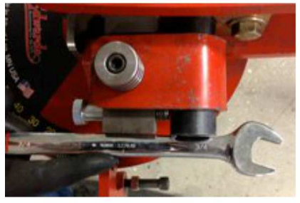
Once the pipe is where you want it in the die, tighten down the set bolt with a 3/4” wrench. Do not over tighten the bolt.
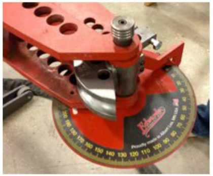
Making a Bend
The pipe bender has an angle finder to locate the degree bend you want to make. To make a 90-degree bend you are going to have to make two 45-degree bends using the step pin on the pipe die.
For your first bend line up the die on the angle finder to 0-degree.
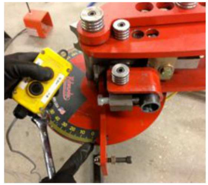
Now press the remote OUT button to start the bend. When you reach the end of the first step, jog the bender back with the IN button to make it easier to remove the step pin. Now adjust the step pin to the next hole in the die to finish the 90-degree bend.
To safely remove your pipe, jog the bender back using the IN button to relieve the pressure on the pipe. Remove the collar, step pin and backstop to remove your pipe.
The dies at Protohaven are for 90-degree bends. To make a 180-degree bend with these dies you must move the pipe forward after the first 90-degrees to ensure that you will not pinch the pipe on the die, which will make it almost impossible to remove the pipe from the bender.
NOTE: The minimum length of pipe to use on the bender is 15”.
No Comments