
Finger Brake Tool Tutorial
A finger brake, also called a box-and-pan brake, is used for making bends in sheet metal. The brake consists of a flat surface onto which the material is placed, and a clamping bar which will come down and hold the material firmly during the bend.
The clamping bar consists of a series of removable metal fingers. These fingers may be removed and rearranged to permit bending of restricted areas of a piece of sheet metal or of already partially formed pieces.
The front plate of the machine is hinged and may be lifted, forcing the material extended over a straight edge to bend to follow the plate. Bends can be made up to any angle with a practical limit of about 120 degrees.
Maximum bending capacity is 16 gauge steel.
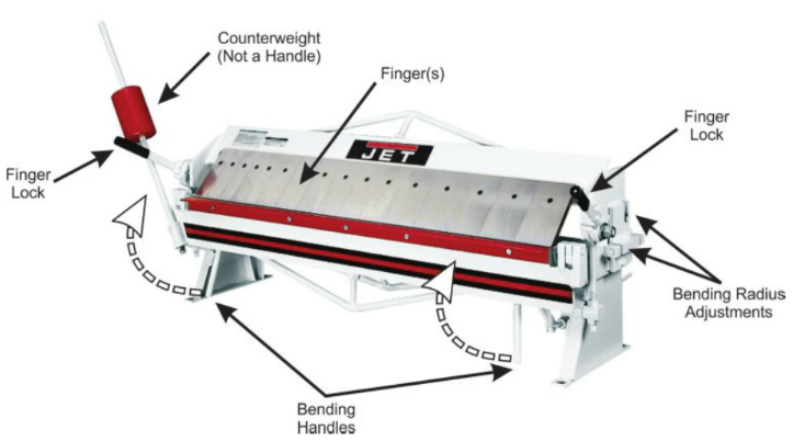
Safety Precautions and Features
- Keep guards in place and in working order
- Keep all body parts away from moving parts and pinch points
- Do not use the counterweight as a handle
- Take care when removing fingers as they are sharp
- Do not exceed maximum capacity of the brake (16 gauge steel)
- Don’t force the machine. It will do the job better and more safely at the rate for which it was designed
- Don’t overreach. Keep proper footing and balance at all times
- Sheet metal has sharp edges. To prevent cuts, use caution when handling
Adjustments
Adjustments can be made to change the bend radius and compensate for material thickness. Find a shop tech to assist with these adjustments.
To remove the fingers for clearance bends use the attached Allen wrench. Loosen the bolt and the finger will come off. Place the fingers below the machine on the base shelf and replace them when bending operations are complete.
Basic Operation
- Unlock both finger locks.
- Adjust to the desired radius and compensate for material thickness. Find a shop tech for assistance with these adjustments.
- Remove necessary fingers for the bend you are making if applicable.
- Place your material flat on the work table surface.
- Align material for the bend location you desire.
- Lock both finger locks.
- Smoothly pull bending handles upwards to create the desired bend angle (travel beyond the bend you desire by a few degrees to compensate for the material springback.
- Return the bending handle to its original location.
- Release finger locks and remove material.
- Replace fingers if applicable.
Notes
- Always bend a few degrees beyond the angle you desire. This will compensate for the natural springback of the metal and your bend will end up at the angle you desire.
- Some bends cannot be made in one movement and must be made incrementally with other bends to reach the desired result.
- Generally, you want to bend from the outside of the part inwards.
- Every parts bending sequence can be quite unique. Take the time to think through the order of operations.
- Materials like aluminum need a larger bend radius as the material can crack with a very tight bend radius.
- The bend radius should be kept the same on all bends if possible to minimize setup time changes.
- For most materials, the ideal inner radius should be at least one material thickness.
- For complex sheet metal geometry, use a 3D program such as Autodesk Inventor to build your part in 3D and then have the software unfold it for you. You can then use this 2D information for layout to create your part in the metal shop. Inventor will do quite a bit of the number crunching for you in regard to bend radiuses and material thickness compensation, and this will be reflected in the 2D drawing you use for layout.
No Comments