
3D (Fusion 360) Design: Wrench Holder
This simple tutorial walks you through designing a 10mm "box" wrench holder with accurate dimensions. You can modify the shapes in this tutorial to quickly create other designs which can then be created using Protohaven's 3D printers, Tormach CNC mill, and other tools that operate with STL or 3D design files.
This tutorial is part of the 2D & 3D Design Bootcamp, and relies on the file from 2D (Inkscape) Design: Basic Wrench. If you'd rather start with this tutorial, be sure to download wrench.svg so you can use it in the steps below.
Fusion 360 requires a (free) license to operate - if you don't have a license already, go here to obtain one.
Setting up the primitivemain shapesbody
It's a good idea to save (Ctrl+S) periodically while designing in Inkscape - the program does sometimes crash and any unsaved data can be lost.
UsingWith Fusion 360 open to a new project, click on thecircle"Create Sketch" tool in the top menu (under SOLID), then click on the bottom (XY) plane.
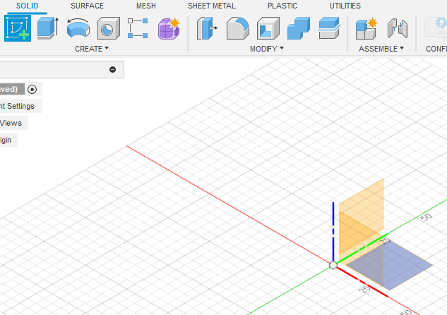
- The view will change to a top-down view. click to expand the CREATE top toolbar menu, then navigate to Rectangle > Center Rectangle. Click the origin on the 3D view, then move your mouse and click again to create a rectangle
toolbarcenterediconson the origin.
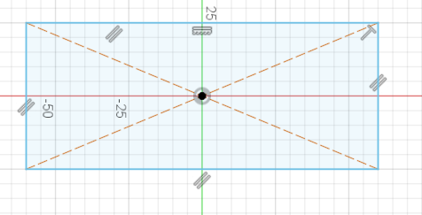
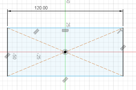
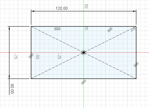
- Expand CREATE again to select Sketch Dimension (or press the D key as a shortcut). Click the top edge of the rectangle, then move your mouse upwards a bit and click again to place the dimension. Type "120 mm" into the value box and hit Enter to set the dimension.
- Use Sketch Dimension again, this time on the left
sideedge of thewindow,rectangle.drawMaketwothiscirclesdimensionand60mm.aPressrectangle of any size.

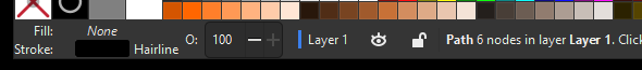
Select all objects and set the stroke to black, and the fill to transparent (the "X" color on the bottom left corner of the page)
Set the dimensions of the rectangle to 75x15mm and the width/height of each circle to 20mm (i.e. 20mm diameter)For rectangle: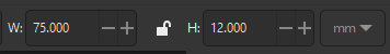
For circles: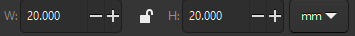
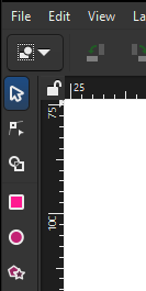
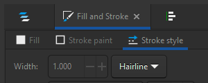
Ensure the rectangle and circle stroke style are all set to "hairline" (Object>Fill & Stroketo open the right panel, then select theStroke Styletab and select "hairline" from the width's units dropdown).
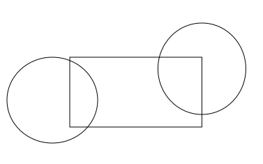
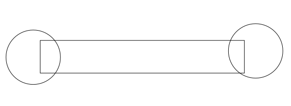
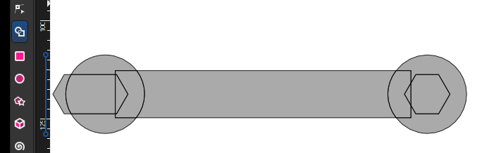
Drag the circles so they hang over either side off the rectangle.
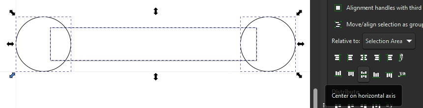
Using the Align and Distribute panel (Accessible from the top menu - Object > Align & Distribute), select all three objects and click "Center on horizontal axis" (the icon in the bottom middle of the Align icon set) to align their vertical centers.


Creating the interior/flats
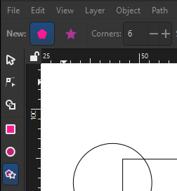
Select the star/polygon tool from the left menu bar. The top toolbar will change to offer some options for the tool; ensure it is set to create a regular polygon with 6 corners.
While holdingCtrlsnap rotation, draw a hexagon with horizontal top and bottom sides. Press escape a couple times to get back toexit theselectorSketch Dimension tool.
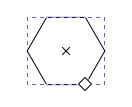
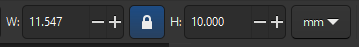
Select the created hexagon, lock the aspect ratio using the padlock icon near the width/height text boxes, and set the height to 10mm. The width should adjust automatically to maintain the shape of the hexagon.

WithAt this point, thehexagonwholeselected,rectangleshift-selectshould be black. Clicking and dragging any part of theleftrectanglecircle.(otherNavigate back tothan theAligndimensions)andshouldDistributedopanel,nothing.thenThissetisRelativecalledtotofullyLast selectedCenterDesigningonpartshorizontalthataxisareandfullyverticalconstrainedaxisisusingrecommended when doing any kind of complex design work, as it saves time when adjusting things later.- Click the
twogreenicons"FINISH SKETCH" checkmark on thepaneltop(you can hover over them to see the nameright of thealignmentscreenoperation).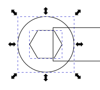
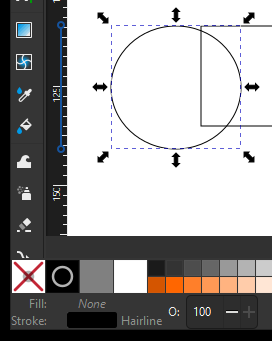
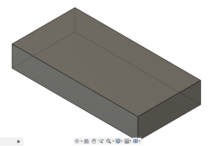
DeselectClickalltheobjects"Extrude"bytoolclickinginelsewherethe top toolbar, then click on thepage.interiorSelect, copy (Ctrl+C) and paste (Ctrl+V)of thehexagonrectangle.nearEnter 20mm, then press Enter to extrude a solid body upwards from thecircle on the right side, then perform the same alignment as in the previous step to align it to the right side circle. You should have something that looks like this:rectangle.
Selectthatthe left hexagon and convert it from a hexagon to a path viaPath>Object to Path. Confirm you nowwe have apathfewselectedoperations,bytakelookingafor "Path 6 nodes in layer..."look at the timeline on the bottom of the application window.
DoubleYouclickcanthegoalready-highlightedbackhexagonand(edit any sketch orclickfeaturethebyNode Tool in the left toolbar). The hexagon will now show drag handlesdouble-clicking oneach of its corners.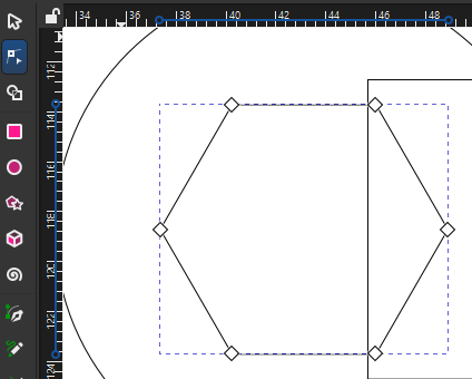
Drag- or shift-select the left three nodes. While holding Ctrl to constrain movement, Click and drag the nodes until they lie outside the left sideone of thecircle.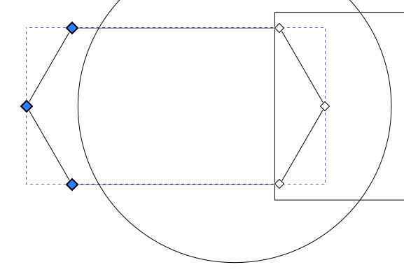
Press the Escape key a few times until the UI stops changing - nothing should be selected, and you should have the Selector Tool highlighted in the left toolbar.


Now


Using Shape Builder to create the final design
Press Ctrl+A to select all objects, then click the Shape Builder tool on the left toolbar. Your design should now be filled in gray and you should see "Add", "Delete", and "Finish"icons in thetoptimeline.toolbar.

With the "Delete" icon selected, click on all of the parts of the wrench we do not want in the finished product. These will disappear from the page: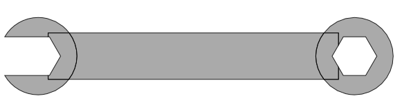
Now click on the Add icon in the top menu bar, thenclick and dragon all parts of the wrench to preserve. These will highlight in blue, and any edge you drag over will be eliminated: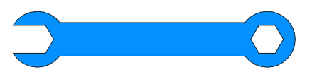
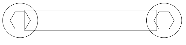
Press the checkmark "Accept" icon next to the Finish label on the top menu bar to lock in your changes. Congratulations, you've made a wrench!


You can compare your work against this reference file: wrench.svg