
3D (Fusion 360) Design: Wrench Holder
This simple tutorial walks you through designing a 10mm "box" wrench holder with accurate dimensions. You can modify the shapes in this tutorial to quickly create other designs which can then be created using Protohaven's 3D printers, Tormach CNC mill, and other tools that operate with STL or 3D design files.
This tutorial is part of the 2D & 3D Design Bootcamp, and relies on the file from 2D (Inkscape) Design: Basic Wrench. If you'd rather start with this tutorial, be sure to download wrench.svg so you can use it in the steps below.
Fusion 360 requires a (free) license to operate - if you don't have a license already, go here to obtain one.
Setting up the main body
- With Fusion 360 open to a new project, click on the "Create Sketch" tool in the top menu (under SOLID), then click on the bottom (XY) plane.
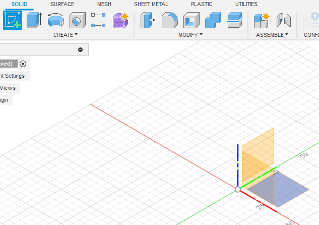
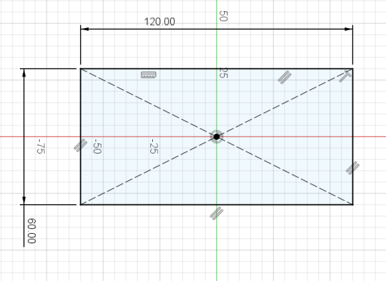
- The view will change to a top-down view. click to expand the CREATE top toolbar menu, then navigate to Rectangle > Center Rectangle. Click the origin on the 3D view, then move your mouse and click again to create a rectangle centered on the origin.
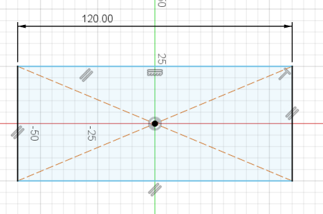
- Expand CREATE again to select Sketch Dimension (or press the D key as a shortcut). Click the top edge of the rectangle, then move your mouse upwards a bit and click again to place the dimension. Type "120 mm" into the value box and hit Enter to set the dimension.
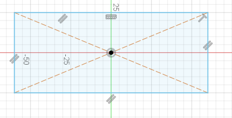
- Use Sketch Dimension again, this time on the left edge of the rectangle. Make this dimension 60mm. Press escape on your keyboard to exit the Sketch Dimension tool.

- At this point, the whole rectangle should be black. Clicking and dragging any part of the rectangle (other than the dimensions) should do nothing. This is called being fully constrained. Designing parts that are fully constrained is recommended when doing any kind of complex design work, as it saves time when adjusting things later.
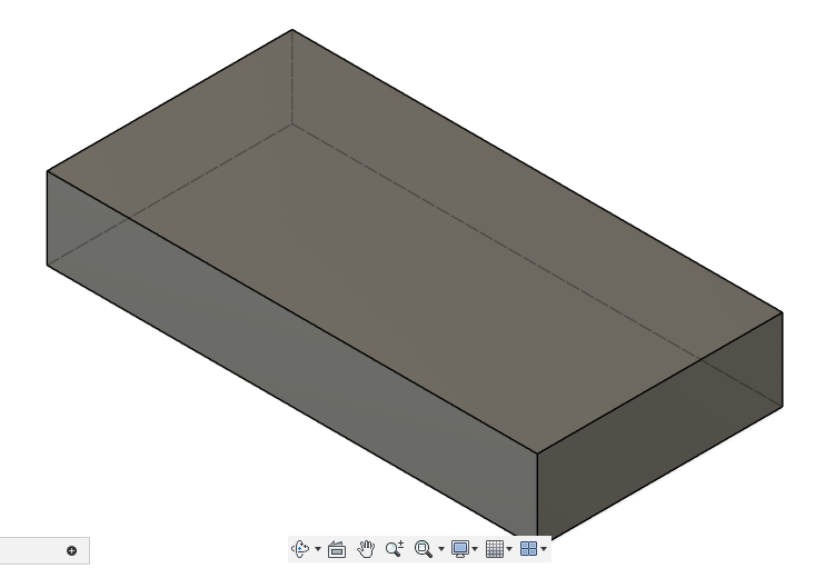
- Click the green "FINISH SKETCH" checkmark on the top right of the screen to finish the sketch. The view should change to an isomorphic (corner) view of your rectangle.
- Click the "Extrude" tool in the top toolbar, then click on the interior of the rectangle. Enter -20mm, then press Enter to extrude a solid body downwards from the rectangle.
Now that we have a few operations, take a look at the timeline on the bottom of the application window. You can go back and edit any sketch or feature by double-clicking on one of the icons in the timeline.


Creating the wrench caddy
- Expand the "INSERT" menu on the top toolbar and select
Insert SVG, thenInsert from my computer. Navigate to the wrench.svg file and open it, then click on the XY plane (as with the first step when creating the rectangle sketch).
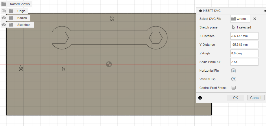
The wrench will appear, but it won't be the right size or in the right place. This is because SVG describes a Scalable Vector Graphic which does not usually include units (e.g. mm or inch) in the file data.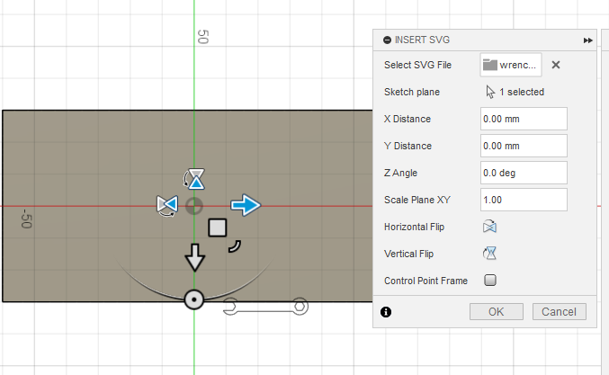
- Set Scale Plane XY to 2.54 to convert from cm to inches, then drag the wrench so it's on the top half of the rectangle. Click OK.

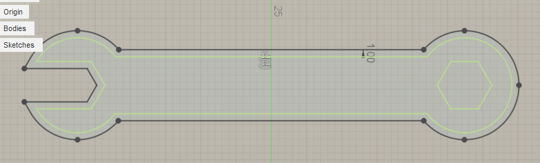
- Under the MODIFY top toolbar menu, click on Offset, then click the outer perimeter of your wrench. set distance to 1mm, then click OK to add a 1mm offset around the existing design. This prevents our wrench from being exactly the same size as our wrench slot, which would produce a "press fit" that makes our wrench difficult to remove and use.
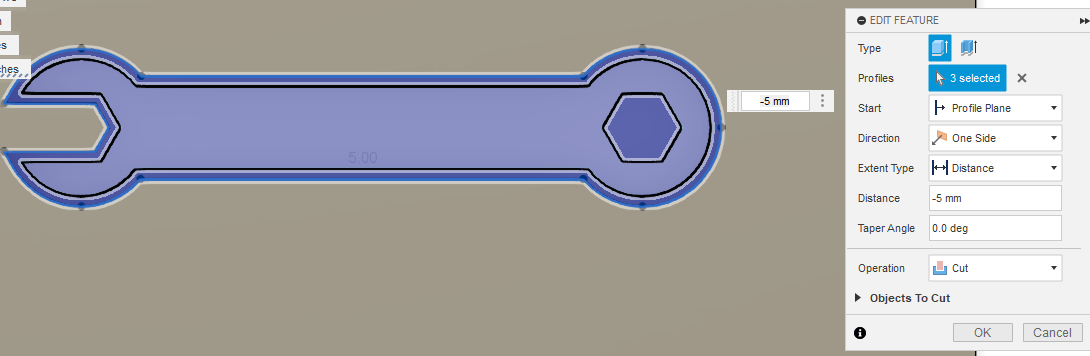
- Click FINISH SKETCH to exit the sketch, then enter the Extrude feature tool just like we did before.
- Left click within the area of the wrench sketch, the as well as the main body of the wrench and the closed hexagon side. Type -3mm to extrude it downwards into the rectangle body. Fusion 360 will automatically perform a Cut operation to remove this material. Click OK to complete the operation.


Adding machine screw and nut trays
Let's use some solid bodies to make trays for some nuts and bolts we can use with the wrench.
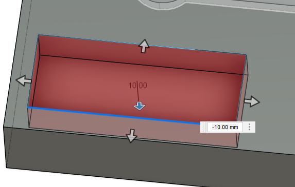
- Under the CREATE menu of the top bar, select "Box", then click on the top face of the rectangular solid we've been working on.
- Click nearby the bottom left corner, then click close to the origin to set the second point of the box. Click and drag the middle arrow that appears, until it's pointing 10mm down into the solid body. Click "OK" on the right-side popup menu to complete the operation.

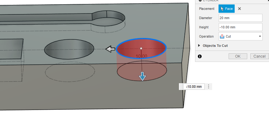
- Repeat these steps two more times, but now using the Cylinder tool under the CREATE menu to create 20mm diameter cylinders that cut 10mm into the part. If you need to get a better look at what you're doing, you can orbit around your part by left clicking and dragging the axis cube with X/Y/Z/FRONT/TOP etc. markings on the top right of the screen.
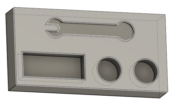
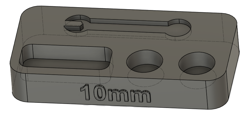
- You should now have a wrench tray and a couple bins for nuts and bolts!
Using primitives instead of sketch/extrude is fast, but you may find it hard to precisely align the features. If you need a primitive exactly positioned somewhere, one way is to create a sketch before creating the primitive, and clicking during creation to reference it to a fully constrained point on the sketch. However, this does somewhat eliminate the benefits of using primitive solids vs just creating a fully constrained sketch and extruding it.


Rounding corners & finishing details
Let's knock off some of the sharp edges on our part to make it nice to handle.
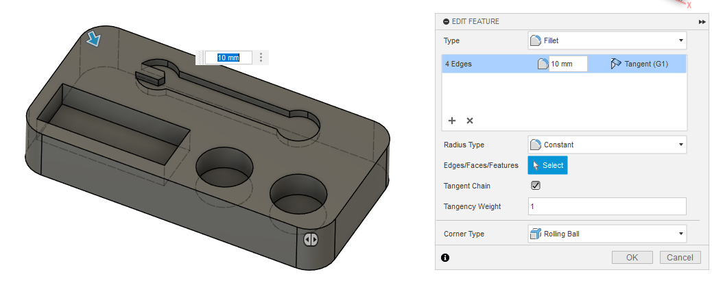
- Under MODIFY, click on the Fillet tool. Orbit the view around your part and click to select each of the four vertical corners of the rectangle. Set the fillet dimension to 10mm, then click OK.

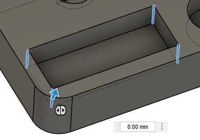
- Do this again to create a 5mm fillet on the interior edges of the rectangular tray on the front left side of the part. If you have trouble selecting individual edges, click and hold over the edge to open a menu that allows you to "select through" the body of the part.

- Create a new sketch on the front face of the part, using the Text tool (under the CREATE menu) to place some custom text. Select center alignment, 10mm Arial Bold for the font, and write "10mm" for the text content.
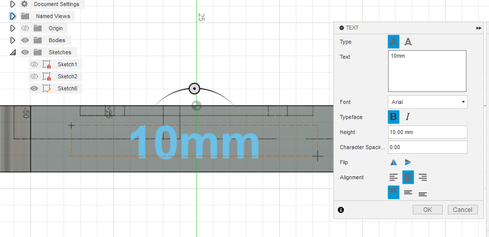
- Press OK, then FINISH SKETCH, then select the text and Extrude it 1mm away from the front surface of the part. You should now have a finished wrench and nut/bolt holder!


Exporting to STL file
- Expand the Bodies folder in the browser overlay, then right click on Body 1 and select Save as Mesh
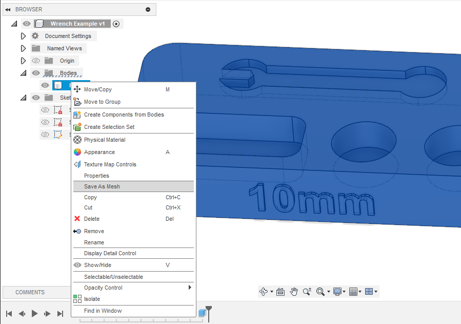
- Under Format, select STL (Binary), then click OK and choose where to save your file. You should end up with something like Body1.stl saved onto your computer.

No Comments