
Tool Tutorial
Tool Tutorial
The Kiln
The kiln is a custom made electric kiln with a programmable PID temperature controller.
Notes
Safety
- Do not leave the building with the kiln running.
- No overnight programs are permitted.
Common Hazards
- Burns or fire from heat exposure, touching hot parts of the oven or workpiece
- Smoke and fumes due to contaminants, inadequate ventilation
- Shrapnel from rapid temperature shocks in brittle materials (e.g. glass) or wet materials (e.g. ceramic that isn't bone-dry)
- Damage to the interior of the kiln from heating fusible workpieces without proper technique
- Damage to refractory (scraping against workpiece, thermal shock, slamming the door etc.)
- Damage to the kiln heater system from prolonged operation at the max temperature
- Pinching/crushing on the door latches
Care
- Minimize the amount of time with heating at high temperatures to prolong life of the heating elements.
- Shut the door gently to prolong life of the door gasket and fire bricks.
Use
Simple Ramp and Soak Program
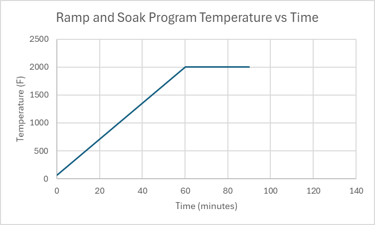
This program ramps from room temperature (68 F) to 2000 F over 60 minutes, holds temperature at 2000 F for 30 minutes, then the program stops and cools to ambient. A plot of time vs temperature should look like this:
|
Note: This is IDEAL |
Here is the data for what actually happens:
|
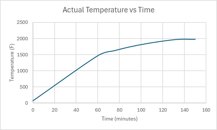 |
Note that you can program the controller to do impossible tasks. Doing this will prevent the controller from executing commands as programmed. In this example, there were two problems:
- The programmed heatup rate was (2000-68)F / 60 min = 32.2 F/min, but the absolute maximum average heatup rate that the kiln can provide in this temperature range was only 23.38 F/min.
- The program called for soaking at 2000 F for 30 minutes, but the kiln never reached 2000 F to start the soak, so the program ran for 150 minutes (before it was shut down manually) rather than the 90 minutes it was programmed to run.
Program Explanation
Ramp: Using the program above as an example, you can program a ramp by setting the temperature for C1 and C2 as different values, then at the end of the time period set for C1, the controller will change the setpoint heating to be at temperature C2 by the end of the time set for C1.
Soak: Just as in the ramp program, once the temperature setpoint for C2 is reached the controller looks ahead to the next temperature setpoint to figure out what needs to happen next. In this example, the temperature setpoint for C3 is the same as the temperature for C2, so the controller will not adjust the temperature setpoint for 30 minutes (the time C2 is programmed to run for).
Stop: the time "-121" in C3 time comes from this equation:
C(stop) time value = - (30 * Command# + NextStep)
In this example: C3 = -(30 * 4(from C4) +1(We want the next step to be C1)) = - (120+1) = -121
Summary:
| Command type | Temperature | Time |
| Ramp | C[a] =/= C[a+1] | Duration of the ramp in minutes |
| Soak | C[b] == C[b+1] | Duration of the soak in minutes |
| Stop | Final desired temperature requiring temperature control |
Calculated via: (30 * Command# + NextStep) |
Other Example Programs
Here is a program that might be used to anneal steel (temperatures are approximate, but are used to determine timing):
| Temperature (F) | Time (minutes) | Explanation | |
| C1 | 68 | 60 | Ramp up to 1450 F |
| C2 | 1450 | 30 | Hold at 1450 F |
| C3 | 1450 | 630 | Ramp cooldown to 1000 F |
| C4 | 1000 | -151 | End of program |
Normalizing steel:
| Temperature (F) | Time (minutes) | |
| C1 | 68 | 70 |
| C2 | 1550 | 30 |
| C3 | 1550 | -121 |
Known Heatup and Cooldown Rates:
Use these to determine program step times.
Heatup Rates: These are the maximum possible heatup rates over timespans. In the future, we will organize these by temperature band for ease of use.
| Time after Start (Min) | Temperature (F) | HUR (F/min) | HUR (F/hr) |
| 0 | 68 | N/A | N/A |
| 60 | 1471 | 23.38 | 1403 |
| 75 | 1625 | 10.26 | 616 |
| 90 | 1749 | 8.26 | 496 |
| 105 | 1846 | 6.46 | 388 |
| 120 | 1925 | 5.26 | 316 |
| 135 | 1981 | 3.73 | 224 |
Cooldown Rates: These are the maximum possible cooldown rates over timespans. In the future, we will organize these by temperature band for ease of use.
| Temp | CDR (F/min) | CDR F/Hr | |
| 0 | 1613 | N/A | N/A |
| 15 | 1429 | -12.26 | -736 |
| 30 | 1291 | -9.2 | -552 |
| 45 | 1204 | -5.8 | -348 |
| 60 | 1114 | -6 | -360 |
| 75 | 1041 | -4.86 | -292 |
| 90 | 980 | -4.06 | -244 |
| 120 | 875 | -3.5 |
-210 |
Consumables
- None
Tooling
- Personal temperature measurement device, if desired. A type-K thermocouple is used for control and display purposes, which has a standard accuracy of approximately +/- 4 degrees F.
Materials
The kiln does not have active ventillation, as such, materials that produce fumes when heated are not permitted.
Prohibited materials include but are not limited to:
- Polymers / Plastics of any kind
- Oil covered metals (degrease before heat treatment)
- Zinc-bearing metal alloys - including brass, bronze, Zamak and "pot metals"
- Radioactive metal alloys
- Combustible materials
- Rubber
- Wood, paper, cardboard, MDF
- Foam
- Textiles or fibers
- Wax
- Painted, coated or varnished objects
- Adhesives
- Lead or lead containing materials
- Sealed or hollow containers
- Materials that can melt onto heating elements
Parts of the Tool
Kiln Anatomy
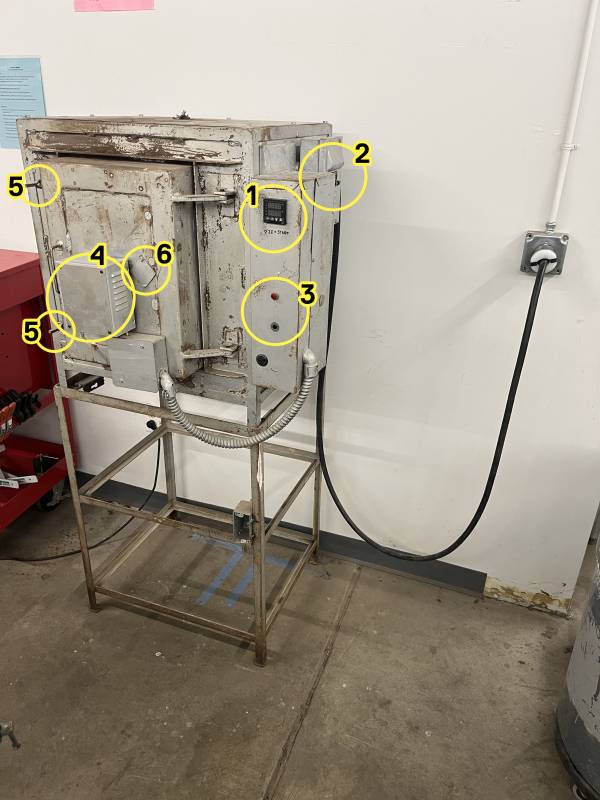
1.
- Controller
- Breaker switches
- Alarm lights
4.(Currently not functional) - Temperature probe
- Latches
- Viewing port
Controller Anatomy
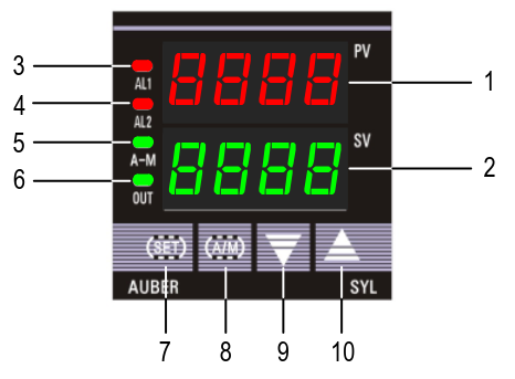
① PV window: Displays the sensorCurrent read out,Temperature, or process value (PV).
② SV window: Displays the Temperature set value (SV) or output value (%).
③ AL1 indicator: It lights up when AL1 relay is on.
④ AL2 indicator: It lights up when AL2 relay is on.
⑤ A-M indicator: The light indicates the controller operating status.
- When A-M
is solid on, program is running. - When A-M is flashing, program is paused.
- When A-M is off, program is stopped.
⑥ Output indicator: It is synchronized with controlControl output (terminal 7 and 8),
and the power to the load.heater.
- When
itthe Output indicator is on, the heater(oriscooler)on. - When the Output indicatoris off, the heater is
powered.
off.
⑦ SET key: In normal operating mode,mode keep(Display mode 1), pressing the SET key momentarilysowill switch the display will be switched between the temperature, step number and
step timer.timer Pressin and hold the SET key for 2s so the controller will switch tosequence.the parameter setting mode. For details, see Figure 3 below.
⑧ A/M key: Programming key; digit shift key.
⑨ DOWN key ▼: Decreases numeric value of the setting value. Pressing and holding the DOWN key for 2 seconds will start the selected program if the controller is displaying STOP or HOLD.
⑩ UP key ▲: Increases numeric value of the setting value. Pressing and holding the UP key for 2 seconds will STOP the current program
Controller Display Modes
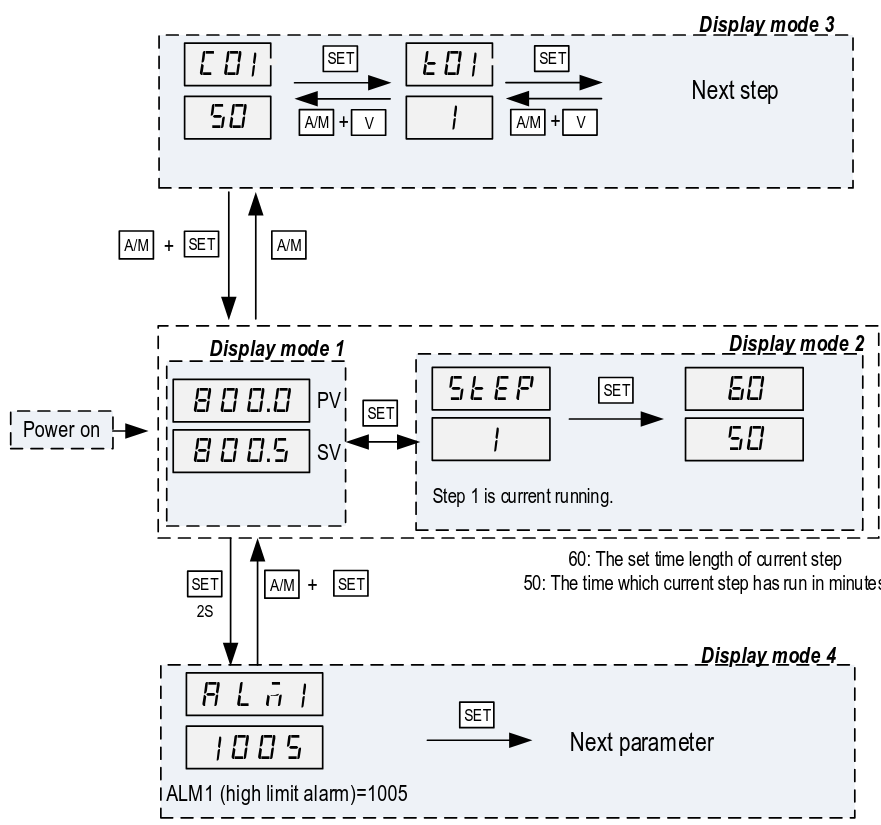
Display modeMode 1: normalNormal operating mode. WhenFollowing power up, the powercontroller iswill turnedbe on,placed thein Display Mode 1. The upper display window shows the measured value (PV) and the lower window shows the four-digit set value (SV).
Display modeMode 2: checkingChecking the step. Press the SET key once to change the display from mode 1 to mode 2. The upper display window shows “STEP” and the lower windows shows the current step number. Press SET key again to show the timer information. PV window shows the set time for the current step. SV window shows remaining time in minutes. Press SET key again to return to the
display mode 1.
Display modeMode 3: programmingProgramming mode. Press A/M key once to change the display from mode 1 to mode 3. As a member, you will only ever need to adjust C01/T01 values.
Do not assume that the C#/T# values are the same since the last time you ran a program.
Display mode 4: Parameter setting mode. Press and hold the SET key for 2 seconds to enter the display mode 4. The top window shows the name of a parameter and the bottom window shows its value. Use the UP and DOWN arrow key the change the value; use the SET key to save the change and go to the next parameter.
These settings are specific to the machine and must not be changed by members. If you suspect a parameter needs to change, please contact a shop tech and ask for help.
To
do
Basic Operation
Setting Alarms
Coming soon.
orderAlarms &can installbe alarmset, buzzer-lightshowever the only indication currently is a small light on the controller.createAlarms aare plotinformative only - they do not impact the operation of heatingthe time to 2000F
4/18 "does it work" test
Setting Alarms
Coming soon.
orderAlarms&caninstallbealarmset,buzzer-lightshowever the only indication currently is a small light on the controller.createAlarmsaareplotinformative only - they do not impact the operation ofheatingthetime to 2000F
T value = time until next step
4/18 "is there an alarm buzzer" test
AL1: Set ALM1 to 1000˚AL2: Set Hy-2 to 10˚
Setup
AskedNote: If you wait too long while setting the kilnprogram, it reverts back to trythe todisplay rampmode towith 2k˚ in 15 minutes. The alarm relays are firing, but no alarm light or buzzer sounds, so we need to get one (or two).
Forge curing schedule
There's a forge which has been lined but needs to be heat-cured.
The official kast-o-lite packet says to ramp down 100˚ per hour, but people online seem to skip this step.2)
Temperature test notes
misc notes
it's possible to store several simple programs; there are 30 steps totalit's possible to set a schedule which is impossible for the machine to achievetelling people in plain english how to set alarms for each type of project is importantthe alarms don't stop anything and are not a safety feature so much as an alertit's possible to observe and change the schedule while it's in progress
To set a singleprogram: temperature:
pressShut the breaker to turn the kiln and controller on.- Press and hold the UP arrow key to stop the last loaded program from running.
- The display should be flashing STOP
- Press A/
M.M to enter programming mode (Display mode 3). The display should show C-1.1 for the last program that was run.- Note: If step 2 was not performed, the controller will display the active step from the last program run.
useSetup/downthearrowstemperature for the first temperature setpoint as follows:- Use the UP / DOWN keys to set
firstthedigit,selectedthendigitpressof the temperature setpoint (Setpoint in fahrenheit). - Press the A/M
to move onkey tonextselectdigit.which digit of the temperature setpoint is being modified. - Repeat steps 4.1 and 4.2 until
lastthedigitdesired temperature setpoint is set.
- Use the UP / DOWN keys to set
- Press the SET key to save the temperature setpoint and advance to the time setpoint.
- Use the UP / DOWN keys to set the selected digit of the time setpoint (Setpoint in minutes).
- Press the A/M key to select which digit of the time setpoint is being modified.
- Repeat steps 5.1 and 5.2 until the desired time setpoint is set.
- Press the SET key to save the time setpoint and advance to the next temperature setpoint.
- Repeat steps 4 and 5 for all desired time and temperature setpoints.
Programs can be set and changed during operation of a program.
Run a Program
To start a program:
- Press and hold the down arrow button for 2
seconds.seconds to start the program. Don'tObservetouchthatanything;thewaitPV display temperature begins increasing.
The controller display returns to Display mode 1 (displays temperature and temperature setpoint) after 10 seconds of inactivity. To view the current step being executed, press the SET key from Display mode 1. Pressing the SET key a fewsecond secondstime will show the programmed time (top number) of the step and itthe shouldelapsed starttime heating.(bottom
Stop ata theProgram
To orstop toa observeprogram:
- Press
asandit cools you can presshold the UP arrow key for 2 seconds toputstop themachineprogram. - The
STOPdisplaystatewill begin flashing STOP.
Shut
To run a pre-created program (i.e. set the current program segment):
PressOpenA/M.theDisplaycircuitshould show C-1breaker.PressShutAMtheagain.kilnDisplay should show T-1door.UseClean up theup/down arrows to enter -X, where X is the step number (i.e. the negative of the step you wish to run). For instance, to run a program at step 5 you would enter -5. This tells the controller to jump to that step.Press and hold the down arrow button for 2 seconds.Continue as with single temperature from step 4.area.
Cleaning
TheUp
kiln
- Remove
resumeany personal belongings from thelastarea
Parameter settings as of 2025-12-02
Lock Values
3) Program AdjustmentWhen Lock = 0, program adjustment is allowed. The operator can view theprogram steps and change the setting. When Lock = 1, 2, 3 and up, programsteps cannot be viewed nor edited.4) Step SelectionWhen Lock = 0 or 1, operator can check the current step number and jump toanother step by changing the step number. When Lock = 2, 3 or up, operator isnot allowed to check the current step number and cannot jump to other steps.
Propose setting LOCK value 0 so program adjustment and step selection, but limited parameter changing. Ensure EP1 is NONE so no adjustment of settings. Would need to set LOCK to 808 to adjust parameters afterwards