
Tool Tutorial
(Link to PDF Tool Tutorial)
Tool anatomy
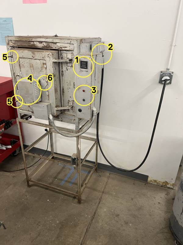
1. Controller 2. Breaker switches 3. Alarm lights 4. Temperature probe 5. Latches 6. Viewing port
Controller Anatomy
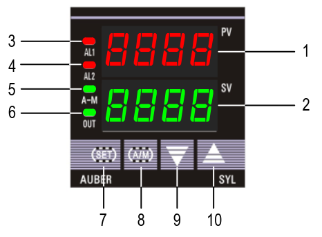
① PV window: Displays the sensor read out, or process value (PV).
② SV window: Displays the set value (SV) or output value (%).
③ AL1 indicator: It lights up when AL1 relay is on.
④ AL2 indicator: It lights up when AL2 relay is on.
⑤ A-M indicator: The light indicates the controller operating status. When A-M
is solid on, program is running. When A-M is flashing, program is paused.
When A-M is off, program is stopped.
⑥ Output indicator: It is synchronized with control output (terminal 7 and 8),
and the power to the load. When it is on, the heater (or cooler) is powered.
⑦ SET key: In normal operating mode, keep pressing the SET key momentarily
so the display will be switched between the temperature, step number and
step timer. Press and hold the SET key for 2s so the controller will switch to
the parameter setting mode. For details, see Figure 3 below.
⑧ A/M key: Programming key; digit shift key.
⑨ DOWN key ▼: Decreases numeric value of the setting value.
⑩ UP key ▲: Increases numeric value of the setting value.
Display Modes
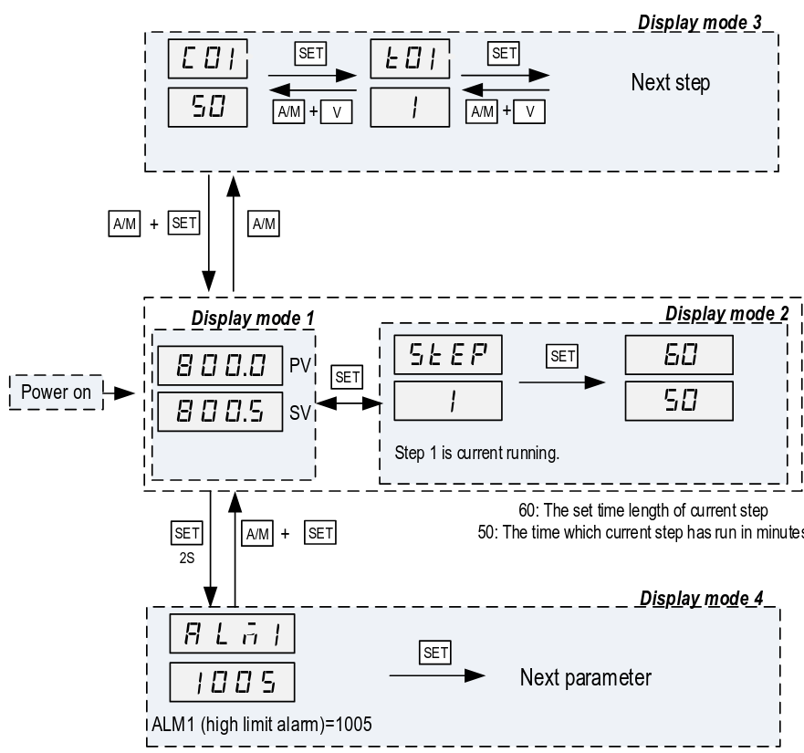
Display mode 1: normal operating mode. When the power is turned on, the
upper display window shows the measured value (PV) and the lower window
shows the four-digit set value (SV).
Display mode 2: checking the step. Press the SET key once to change the
display from mode 1 to mode 2. The upper display window shows “STEP” and
the lower windows shows the current step number. Press SET key again to show
the timer information. PV window shows the set time for the current step. SV
window shows remaining time in minutes. Press SET key again to return to the
display mode 1.
Display mode 3: programming mode. Press A/M key once to change the
display from mode 1 to mode 3. This mode is used for setting and changing the
program.
Display mode 4: Parameter setting mode. Press and hold the SET key for 2
seconds to enter the display mode 4. The top window shows the name of a
parameter and the bottom window shows its value. Use the UP and DOWN arrow
key the change the value; use the SET key to save the change and go to the
next parameter.
To do
- order & install alarm buzzer-lights
- create a plot of heating time to 2000F
4/18 "does it work" test
T value = time until next step
| Step | Set Temp (˚F) | T value | Check time | Check temp | Notes |
|---|---|---|---|---|---|
| 1 | 80 | 15 | 10:33 | 75 | |
| 2 | 300 | 15 | 10:48 | 295 | 213˚/15min = ~14˚/min |
| 3 | 0 | -121 | 11:03 | 265 | it definitely works |
4/18 "is there an alarm buzzer" test
-
AL1: Set ALM1 to 1000˚
-
AL2: Set Hy-2 to 10˚
Asked the kiln to try to ramp to 2k˚ in 15 minutes. The alarm relays are firing, but no alarm light or buzzer sounds, so we need to get one (or two).
| Step | Temp (˚F) | T value | Check time | Check temp | Notes |
|---|---|---|---|---|---|
| 1 | 80 | 15 | step skipped | ||
| 2 | 300 | 15 | 11:40 | 300 | AL2 light on, no buzzer |
| 3 | 2000 | 180 | 12:00 | 550 | proceeding to “can we get to 2k” test |
| 12:03 | 600 | ||||
| 12:07 | 661 | ||||
| 12:15 | 766 | ||||
| 12:21 | 839 | ||||
| 12:27 | 896 | ||||
| 12:34 | 958 | ||||
| 12:54 | 1099 | AL1 light on, no buzzer | |||
| 1:25 | 1250 | ||||
| 1:35 | 1284 | ||||
| 1:47 | 1331 | ||||
| 2:09 | 1386 | ||||
| 2:11 | 1400 | ||||
| 2:32 | 1454 | ||||
| 2:51 | 1492 | ||||
| 3:45 | ~1570 | hovering around here, jumping rapidly up and down. the area around the kiln is warm. this is about the functional limit of this configuration. | |||
| 4 | 80 | -121 | |||
Forge curing schedule
There's a forge which has been lined but needs to be heat-cured.
| Step | Temp (˚F) | T value | Notes |
|---|---|---|---|
| 1 | 100 | 60 | ramping up 100˚/hr |
| 2 | 200 | 60 | |
| 3 | 300 | 60 | |
| 4 | 400 | 60 | |
| 5 | 500 | 60 | |
| 6 | 600 | 60 | |
| 7 | 700 | 60 | |
| 8 | 800 | 60 | |
| 9 | 900 | 60 | |
| 10 | 1000 | 60 | |
| 11 | 1100 | 60 | |
| 12 | 1200 | 30 | holding for 1/2 hour for 1/2“ of material |
| 13 | 80 | -121 | stop |
The official kast-o-lite packet says to ramp down 100˚ per hour, but people online seem to skip this step.
Temperature test notes
| Temperature | Time |
| 250F | T=0 |
| 1500F | T+45min |
| 1750F | T+70min |
| 2000F | T+140min |
| Ramp down to 1500F | +15 mins |
misc notes
-
it's possible to store several simple programs; there are 30 steps total
-
it's possible to set a schedule which is impossible for the machine to achieve
-
telling people in plain english how to set alarms for each type of project is important
-
the alarms don't stop anything and are not a safety feature so much as an alert
-
it's possible to observe and change the schedule while it's in progress
To set a single temperature:
- press A/M. Display should show C-1.
- use up/down arrows to set first digit, then press A/M to move on to next digit. Repeat until last digit is set.
- Press and hold the down arrow button for 2 seconds.
- Don't touch anything; wait a few seconds and it should start heating.
- You can turn the machine off at the breaker, or to observe the temperature as it cools you can press the UP arrow key for 2 seconds to put the machine into STOP state
To run a pre-created program (i.e. set the current program segment):
- Press A/M. Display should show C-1
- Press AM again. Display should show T-1
- Use the up/down arrows to enter -X, where X is the step number (i.e. the negative of the step you wish to run). For instance, to run a program at step 5 you would enter -5. This tells the controller to jump to that step.
- Press and hold the down arrow button for 2 seconds.
- Continue as with single temperature from step 4.
Parameter settings as of 2025-12-02
Lock Values
3) Program Adjustment
When Lock = 0, program adjustment is allowed. The operator can view the
program steps and change the setting. When Lock = 1, 2, 3 and up, program
steps cannot be viewed nor edited.
4) Step Selection
When Lock = 0 or 1, operator can check the current step number and jump to
another step by changing the step number. When Lock = 2, 3 or up, operator is
not allowed to check the current step number and cannot jump to other steps.
Propose setting LOCK value 1, so no program adjustment but yes step selection. Ensure EP1 is NONE so no adjustment of settings. Would need to set LOCK to 808 to adjust anything after