
Tool Tutorial
Morgan Industries G-100T Injection Molding Machine
The injection-molding machine forms plastic parts by melting plastic and forcing the plastic into a
multi-plate mold that is held in a powerful clamp. After the plastic solidifies, the clamp is released,
allowing the finished part to be removed from the mold.
The basic cycle is clamp, melt, inject, pack, solidify, unclamp, eject.Clamp:
- Clamp: The two (or more) parts of the mold are brought together and held under pressure by a
strong clamp.Melt: - Melt: Feed stock material is brought up to melting temperature and becomes a viscous liquid.
This is often called “the melt.”Inject: - Inject: The melt is forced into the mold cavity, filling it completely.
Pack: - Pack: The melt is held at pressure inside the mold until the gate solidifies. (The “gate” is the final
orifice that material flows through into the cavity.)Solidify: - Solidify: The material is allowed to harden in the mold. As it solidifies, it will shrink. The amount of
shrink depends on the material and your process.Unclamp: - Unclamp: The parts of the mold are pulled apart to allow the work piece to be removed.
Eject: - Eject: The work piece is removed from the mold and allowed to continue to cool. It may shrink
further as it cools.
On the G-100T, all of these processes are manually controlled. This provides great flexibility and
allows you to use complex molds without having to do any complicated controller programming.
In injection molding, the key to quality is a consistent process. Since with our machine you are the
controller, you will get the best results by developing a rhythm and keeping up a comfortable and
consistent pace as you make parts.
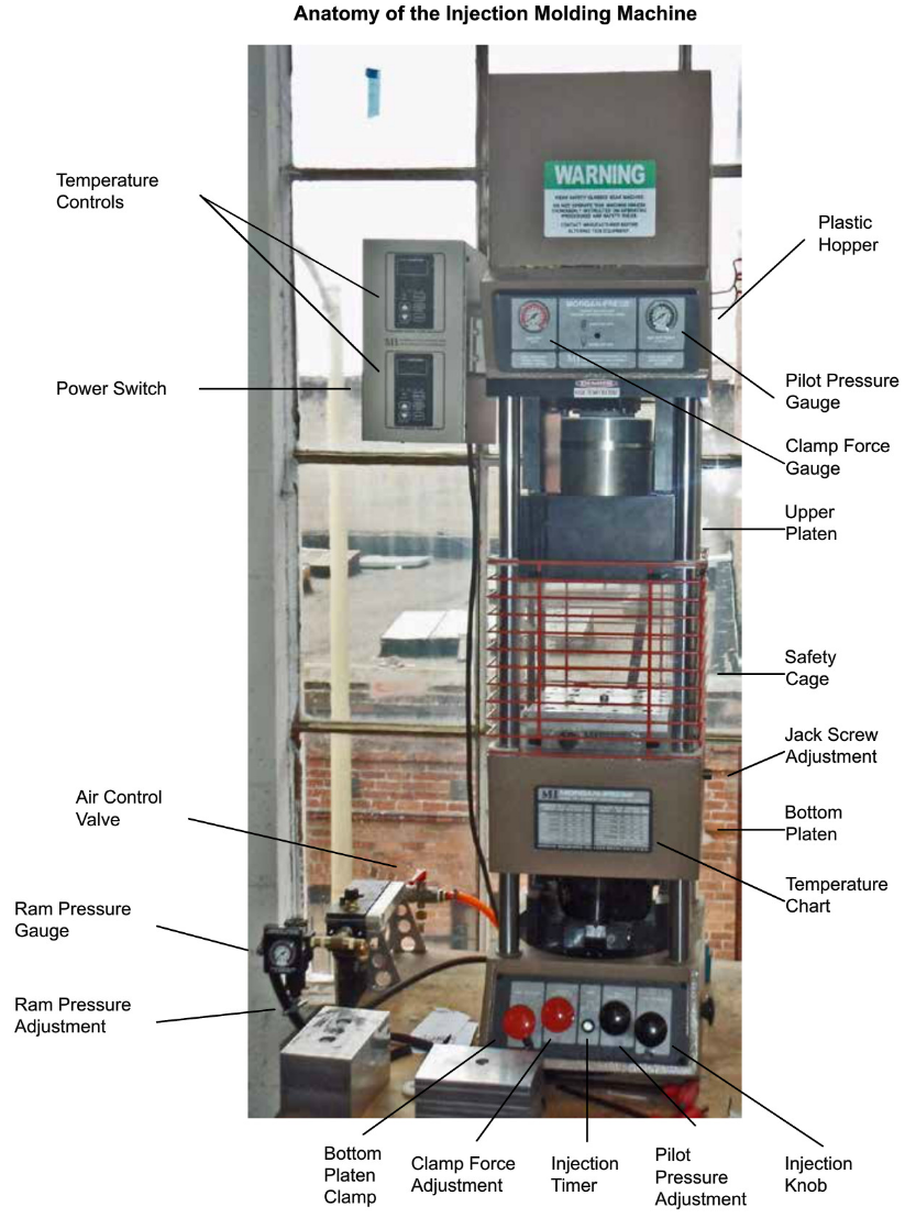
Injection Molder
Safety and Procedures
«
- Some parts of the machine are hot and can cause severe burns
* - Hot plastic is sticky and can cause severe burns
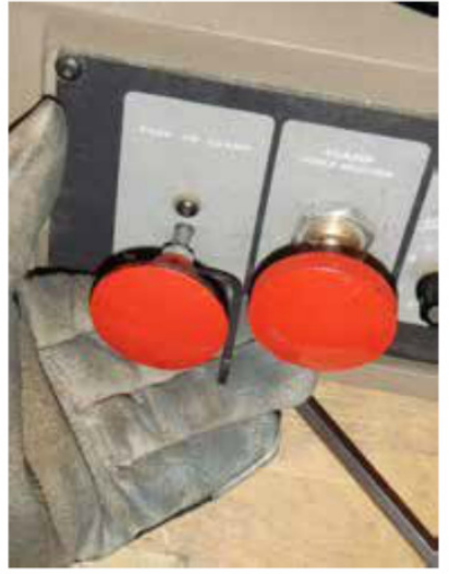
» - Wear leather or heat-resistant gloves to protect your hands from hot molds and plastic
« - The machine has a powerful clamp that can cause crushing injuries. Do not defeat the safety
interlock, and watch for fingers around the lower platen when clamping and unclamping« - The machine has a powerful ram that can cause crushing injuries. Do not defeat the safety
interlock. Do not open the feed chute door before the ram has completed its return stroke+ - Know what, if anything, your chosen material out-gasses during the melt phase and ensure
adequate ventilation* - Know the correct process temperatures for your material. Avoid excessive process
temperatures. Some resins give off noxious fumes when overheated, and all will quickly
degrade. Excessive temperatures don’t help — imagine melting ice cubes — water at 80°F isn’t
any more liquid than water at 40°F — so, too, with plastic* - Do not process “mystery material.” It may out-gas unacceptable fumes, or may be corrosive.
- Know the properties of your material and obtain a data sheet from the manufacturer, if possible.
« - DO NOT RUN SHAPELOCK - it is a very low-temperature plastic not suitable for injection
molding
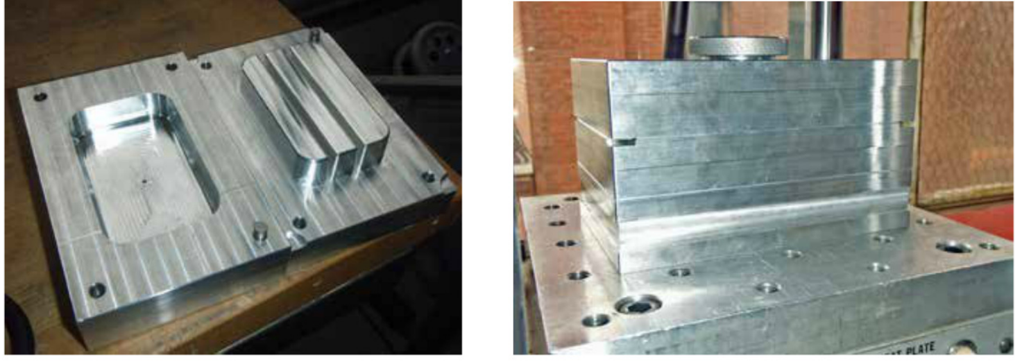
Basic Anatomy of a Mold Figure
Making parts with an injection-molding el
machine requires that you bring a mold Sprue bush'“&af //
to use with the machine. There are many
subtleties in mold design, and TechShopoffers a separate mold making class todig into those design issues. Indesign; this SBU,wetool aretutorial only going to covercovers the basic
parts and nomenclature of a mold.Sprue-GateMoldMating Ring
Figure 1 shows the cross-section of a elAryGap
simple two-part manual mold for a cup.cup:
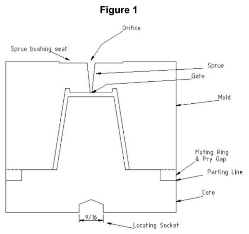
Bottom Plate
The bottom plate has a locating socket 9/16
that centers the mold over the locating Trlocating Seckst
pin on the mold heater.
The core that forms the interior profile of the work piece is, in this case, part of the bottom plate.
Where the top and bottom plates meet is called the parting line. The top and bottom plates of a mold
need to meet with correct alignment. In this mold, a simple step is turned in the bottom plate that
mates with a ring turned in the top plate.
Top Plate
The top plate molds the exterior profile of the part. The locating ring turned in the top plate is milled
through on each side to provide places to insert tools to pry apart the two parts of the mold. The
injector nozzle on the G-100T is a 1” diameter ball with a 3/16” orifice. This mold is designed to use
a sprue bushing (not shown) between the nozzle and the mold. The sprue carries the melt from the
nozzle to the gate.
Molds should be vented to allow air to escape when material is injected. Vents are typically 0.002”
deep channels milled along the parting line from an edge or corner where air would be trapped. For
the class mold, the vents were machined from the edge of the part to the pry gaps for simplicity.
Other Features
More sophisticated molds have additional features. Runners distribute material from the sprue to the
gates in multi-gate or multi-cavity molds. Core pulls are additional parts of a mold inserted from the
side to create more complex features than a two-piece mold will allow. Ejector pins are used to pop
the part from the mold when the machine unclamps. Inserts are components placed in the mold to
become part of the finished work piece.
Using the Injection Molder
The injection molder requires many steps to set it up. It may seem a little overwhelming at first, but it
will get easier each time you use the machine.
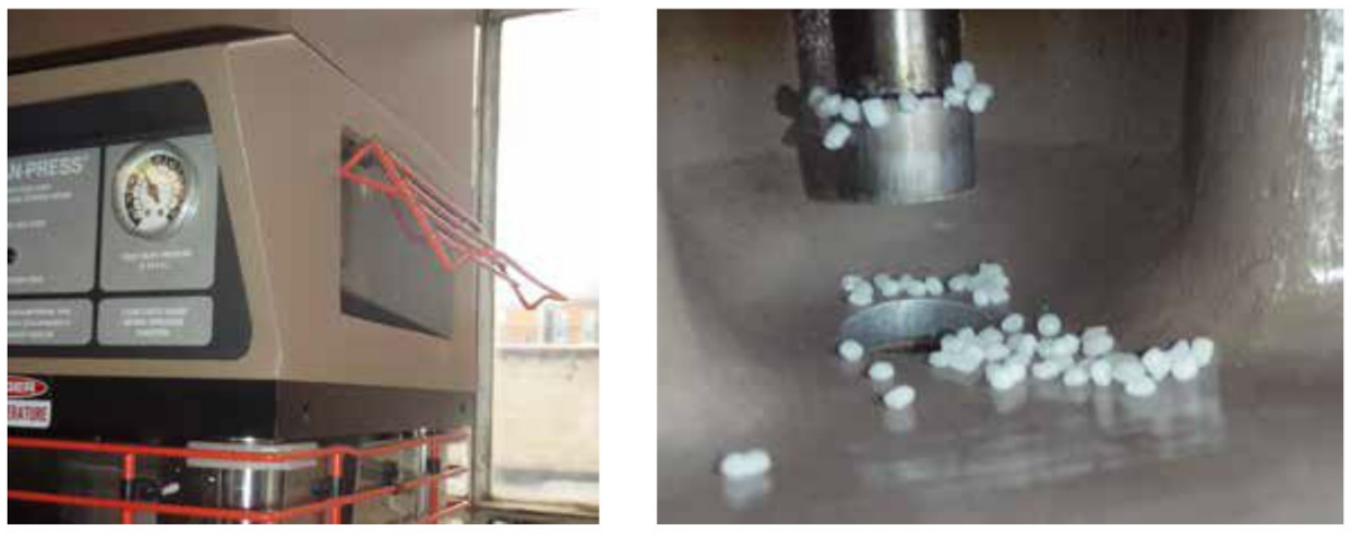
Remove Leftover Plastic and Fill Hopper
Start by checking the hopper for plastic left over from the previous user. If there is plastic in the
hopper, you'll have to heat up the machine up and purge the hopper before adding your own plastic,
which is covered a little later on. If there is no leftover plastic in the hopper, fill the hopper with the
plastic you'll be using.
Preheat Injection Molder
1.
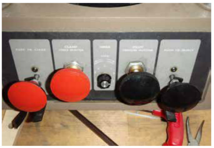
- Turn ON the injection molder by flipping the switch on the side of
the temperature control housing.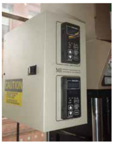
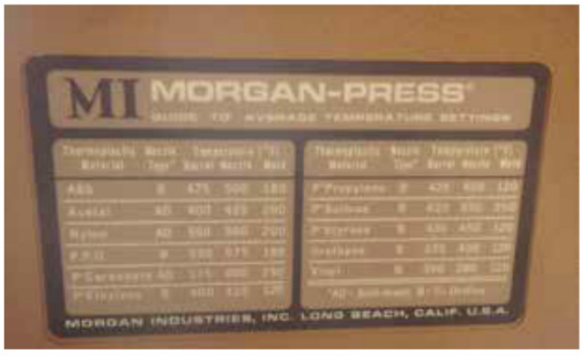
- Adjust the temperatures to match the material you will be
injecting based on the chart on the front of the machine.
- Begin heating the
heater block to the
correct temperatureMORGAN-PRESS ;pbtrrsy: <31 s AR e At o efor your plastic. Thee ture tvaumold, injectornozzleMa___wevei___.._f_.:_:.
nozzle and
heater takee e TGabout 20 minutesT LNto heat up, so be careful not to burn yourself on
anything while setting up the rest of the machine.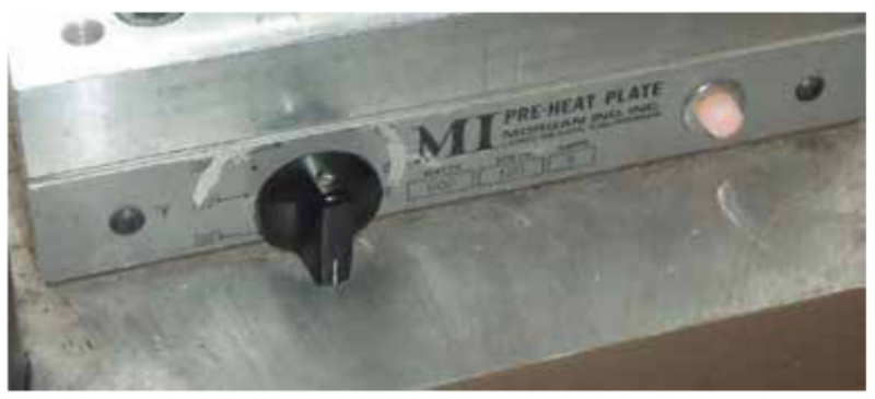
- Connect the machine to a shop air
supply, and turn the air on to the
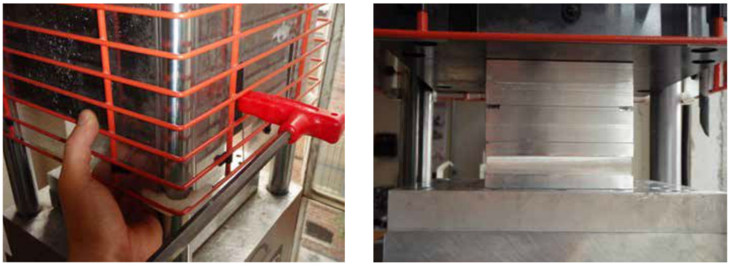
machine using the valve in back.Underneath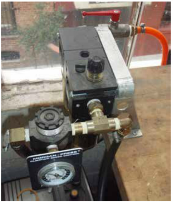
- Open the material hopper cage. There is a safety device that will not let the machine activate
the plastic injection stroke when the hopper cage is open, which makes the machine much
safer while your hands are inside it and in range of the injection nozzle.

2.
3.

4.

5.
Set Up Mold
1.
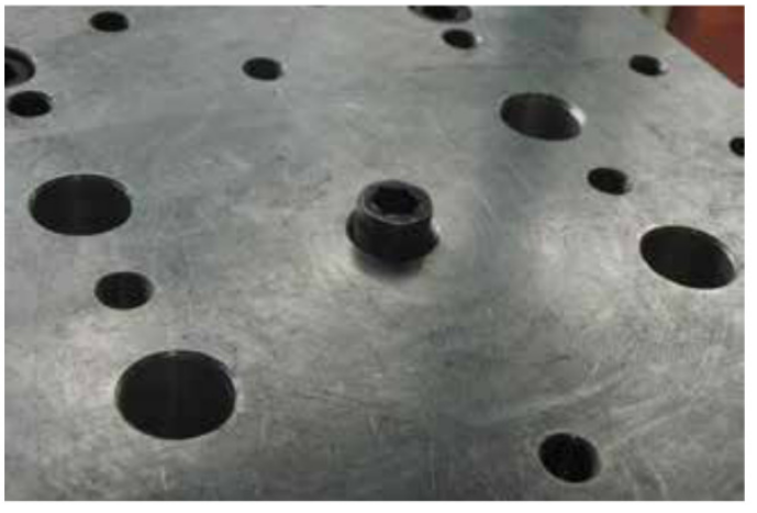
- Insert the locating bolt into the heater block on the bottom platen. The locating bolt keeps your
mold centered under the injection nozzle.
- Place the riser block onto the locating bolt
and spin it to make sure the locating bolt in
the riser stays centered. Depending on the
height of your mold, you may not need a
riser block. Make sure there isn’t any foreign
material on the riser or heater block surfaces.
The riser block should spin freely about
the locating bolt and should not rock when
applying pressure to one side or the other.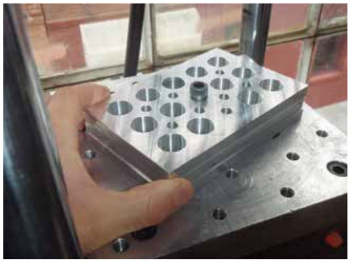
- Carefully put the two halves of the mold
together. Any scratches inside the mold will
leave marks on your molded parts. Place
the sprue bushing on the top of the mold
and place the mold on the riser block. Check
for any gaps or uneven parts resulting from
misalignment or foreign material on the mold.
- Adjust the clamp force to 10 tons by
turning the clamp force knob. Ten tons is
the maximum clamping force that may be
placed on the injection nozzle. Depending
on the design and size of your mold, you
may need to use more or less pressure.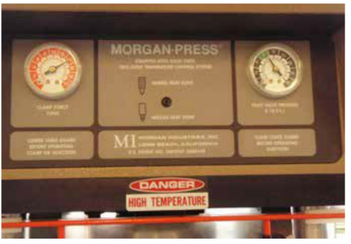
- Adjust the Pilot Pressure to 6.

- Check to make sure the upper platen is
fully raised. If it is not, loosen the four bolts
holding it in position. Be sure to support the
upper platen when loosening the last bolt,
since it is very heavy. Let the platen fall as
far as it can, then slide the safety cage down
to reveal the backing bolts at each corner
and thread them all the way up into the
machine.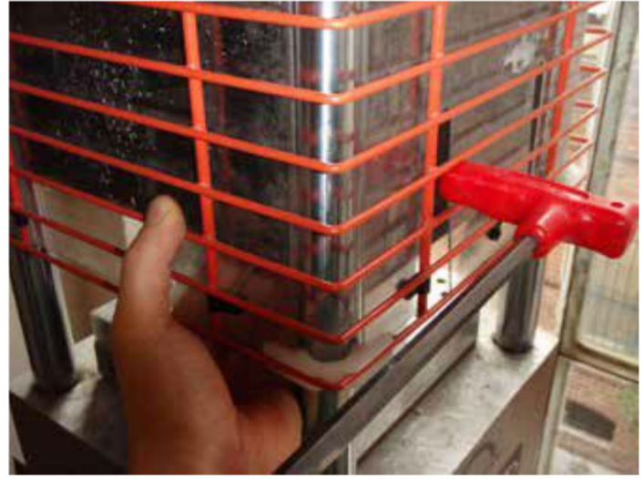
- Raise the safety cage (it may take quite a bit
of force to engage the catch), then raise the
upper platen as far as it will go and clamp
it in place by
tightening one bolt.bolt.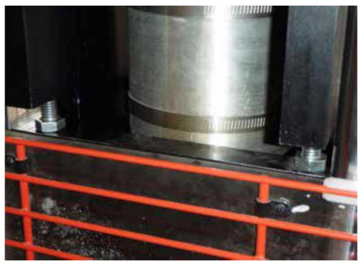
- Remove the
mold from the
machine (use
gloves; it will be
warm), lower
the safety cage,
release the
safety on the
clamp knob,
and pushitinit in to
raise thebottomplaten.bottomplaten.

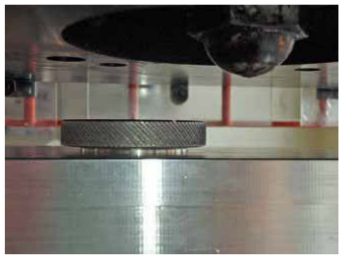
- Raise the safety cage, place the mold and
sprue bushing on the riser block to check
clearances. There should be about 1/4”
between the top of the assembly and the
injection nozzle. If there is not enough
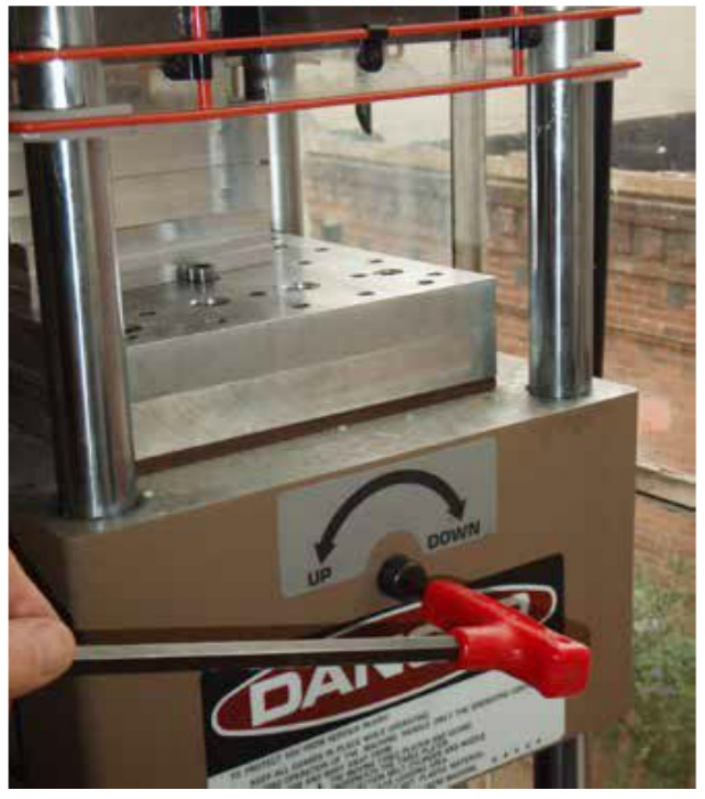
clearance, lower the bottom platen by
turning the adjustment screw on the side of
the machine.
- Lower the safety cage and pull the clamp
knob out to lower the bottom platen. Place
the mold over the locating bolt on the
riser block. Spin the mold to make sure
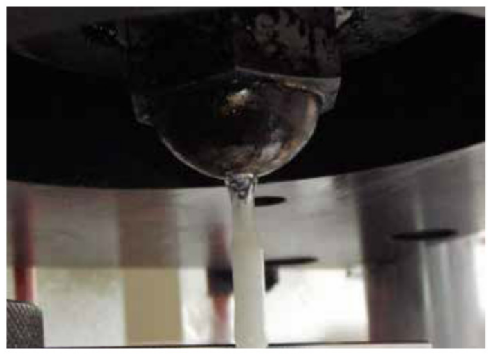
it's centered in the machine. Remove any
plastic dripping from the injection nozzle with
needle-nose pliers. Close the safety cage,
release the safety, and push the clamp knob
in to raise the bottom platen.
- Raise the safety cage and raise the bottom
platen using the adjustment screw on the
side of the machine until the mold contacts
the injection nozzle. Tighten the adjustment
screw further until the mold does not spin on
the riser block.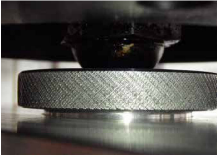
- Support the upper platen and loosen the side slide bolt. Do not let the platen fall on the mold.
Place the upper platen on top of the mold and jiggle it to seat it fully on the mold. Tighten the
four side slide bolts to hold the upper platen in place.
- Lower the safety cage and then lower
the four corner bolts until they are seated
on top of the platen finger tight. (Using a
wrench on the bolts may cause the platen
to become crooked, possibly damaging
the machine or your mold.)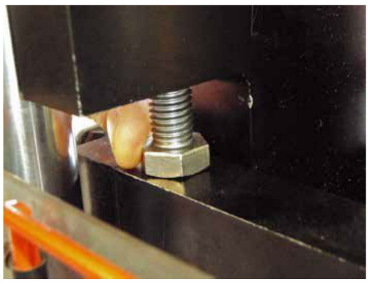
- Now that the upper platen is in place, it's
time to adjust the clamping force. Lower
the safety cage and pull the clamp knob
out to lower the bottom platen. Adjust your
clamping force to what you’ll be using
while creating parts. Raise the bottom
platen using the adjustment screw on the
side by a 1/4 turn and push the clamp
knob. There will be an audible thump
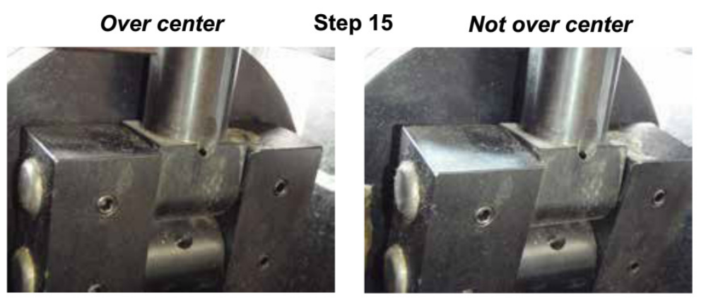
when the jack screw locks in place at the correct clamping force. - If you do not hear a thump while adjusting, check to make sure the jack screw has gone over
center. If it has not, lower the platen adjustment until the jack screw goes over center, and
raise it a 1/4 turn at a time
until you hear the thump.Over center Step 15 Not over center
Clamp and unclamp
the mold a few times to
make sure the thump is consistent.
consistent.Left: The jackscrew is over center,
specified.
contacting the pneumaticcylinder
cylinder. Right: The jack screw is not quite
touching and not capable of holding
the clamping forcespecified
2.

3.
4.

5.
6.

7.

8.
9.

10.
11.

12.
.

14.
15.
Set Up Plastic Injection
Now that the mold is set up, you can set up the
plastic injection.1.
- Start by adjusting the ram pressure.
Ram pressure controls how fast the ram
moves as well as how much pressure the
plastic being injected puts on the mold.
Figuring out how much pressure to use is a
combination of science, art and experience.
A good starting point is 3000 PSI. Adjust
the pressure using the knob under the ram
pressure gauge.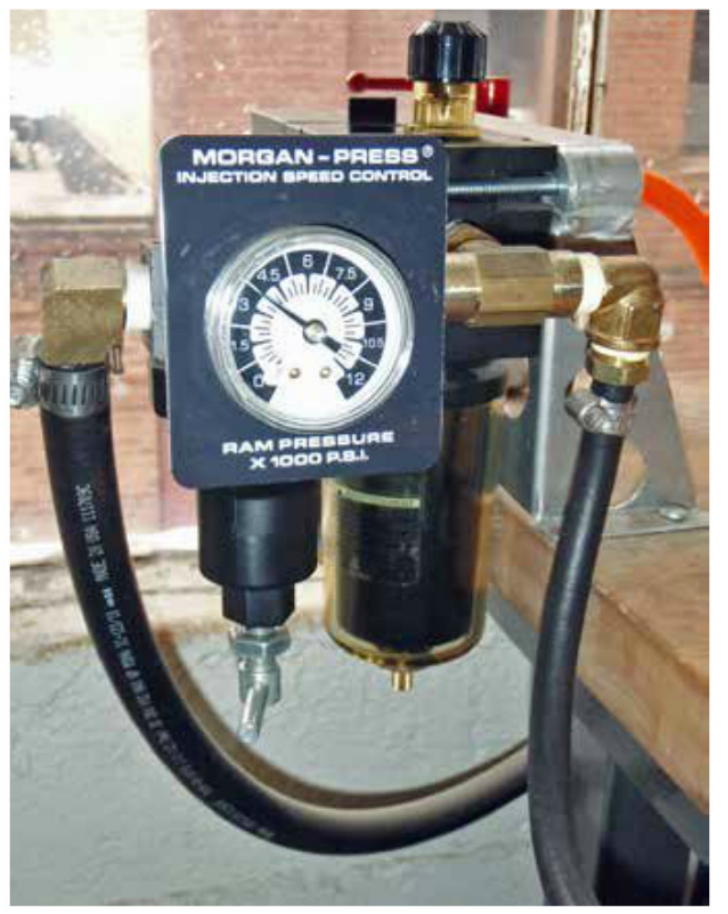
- Remove the mold and riser plate from the
heater block and lower the safety cage.
Close the hopper cage to enable the plastic
injection stroke. Release the safety and
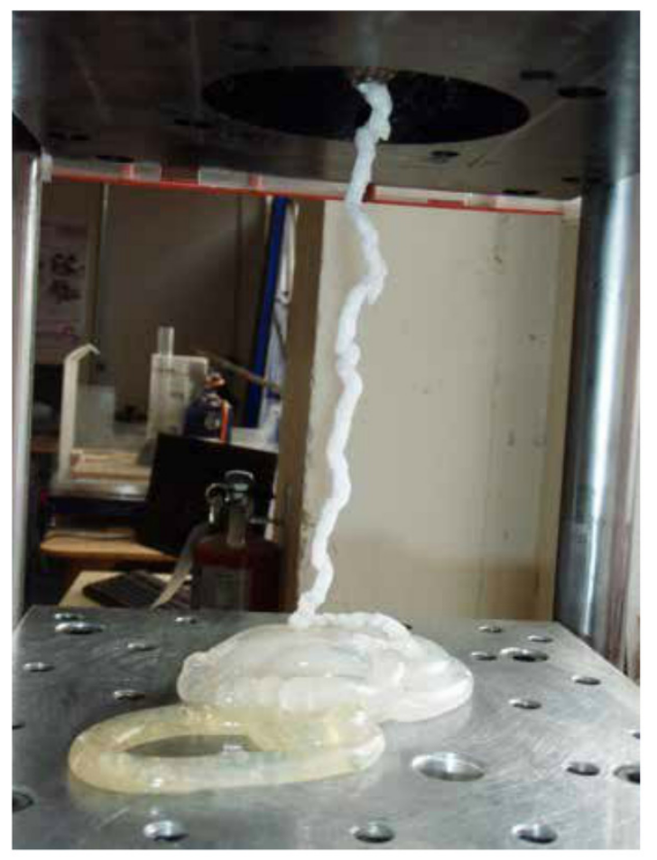
push the inject knob in. Hot plastic should
come out of the injection nozzle similar to
a hot glue gun. This will help purge any
plastic left over from previous users as well
as any burnt material.
- Lift the safety cage and clear out the plastic
using a tool (e.g., pliers) instead of your
hands. The plastic will be very hot and
gooey, and may cause severe burns even if
you’re wearing gloves.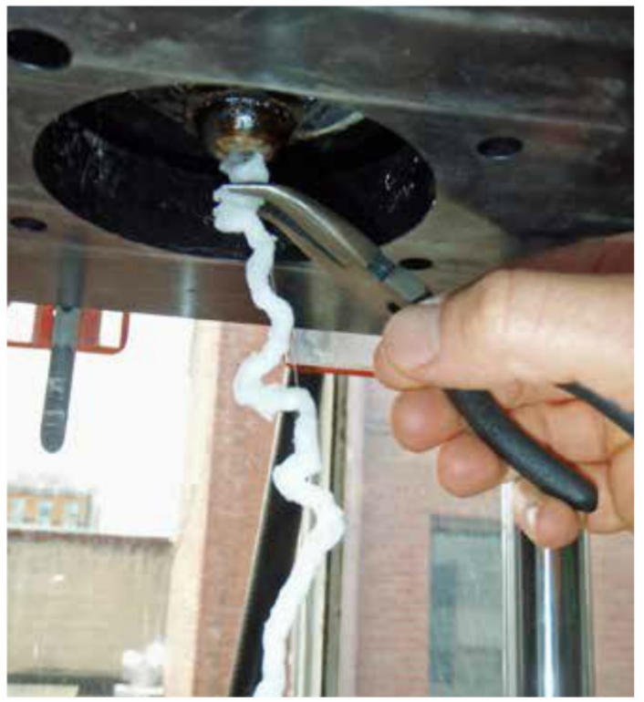
- Place the riser block, mold and sprue bushing
in place over the heater block. Make sure there Step 6
aren’t any gaps between any of the pieces and that
everything is centered on the locating bolts.5. - Lower the safety cage and press the clamp knob to
clamp the mold. Double-check the ram speed gauge,
clamping force gauge and pilot pressure gauge.6. - Turn the small timer knob all the way clockwise until
it stops. Do not apply too much force since it is easy
to break the timer attached to the other side. The
timer comes in handy when making larger quantities
of parts and you know how long the injection cycle
should last.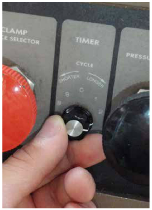

2.
3.

4.

Make Some Parts
1.
- Release the safety on the inject knob and push it in
for about five seconds. It should take the mold about
this long to fill and begin to solidify.2. - Release the knob and wait another five seconds.
This keeps pressure on the plastic in the mold and allows the plastic to fully solidify.3. - Pull the clamp knob out to release the bottom platen and raise the safety cage. Carefully
remove the mold using gloved hands. Twist the sprue bushing several times to sever the
plastic holding it to the mold and place it back on the heater block to help keep it warm for
the next part.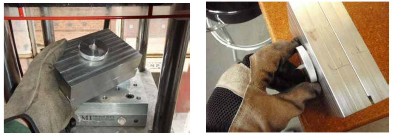
- Carefully split the mold halves apart and pop the molded part out. You may need to use a
screwdriver or other prying implement, but be careful to not damage the mold. You can use
blasts of air or gentle persuasion with a screwdriver to pop the molded piece off the mold.
Do not use too much air since it will cool down the mold. - Chances are, the first part will not come
out right. It may take a few tries to get
everything up to temperature and to find
the right injection time, speed and clamping
force. Consult the troubleshooting guide
(locatedfurtherat the back ofin thishandout)document) and
adjust accordingly.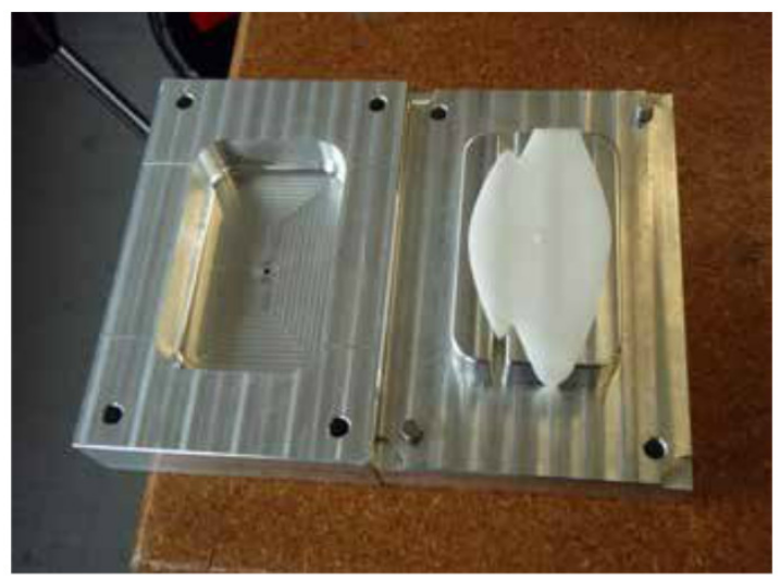
- Keep the hopper full while using the
injection molder. If smoke begins to come
out of the hopper opening, the plastic level
has fallen too far. Depending on the size of
your parts, you may need to add plastic as
frequently as every two or three parts.

4.
.6.

Cleanup and Shutdown
1.
- Scoop out any unused plastic from the hopper. Remove your mold and riser block, lower the
2.3.4.
safety cage, and run a few injection cycles
to purge any plastic left over in the hopper.
- Loosen the four side slide screws to lower
the upper platen, spin the four corner bolts
all the way in, and lift and secure the upper
platen in its fully raised position. - Lower the bottom platen, turn off the heater
block and lower the safety cage. - Turn OFF the air to the machine. Turn OFF
the machine power, and disconnect the air
supply at the source.
Troubleshooting
Issue
Bottom platen doesn’t move when
the clamp knob is pushed in.
Ram
Is the safety cage all the way down,down, engaging the safety interlock?
Ram doesn’t operate when you engage the injection valve.
interlock?
Is the door to the feed chute closed, engaging the safety
interlock? Is the pilot pressure high enough?
Lower platen stalls coming down when disengaged.
The safety cage should slide smoothly on the stanchions,
but sometimes it sticks. When it sticks, it causes the safety
interlock to trip, cutting off the clamp piston’s air supply. Helping
the cage down by hand is a quick fix. The most likely cause is
contamination of the stanchions by over-sprayed mold release
or other foreign material. Wipe down the stanchions with WD-40
to remove the contamination and lubricate the stanchions.
Short shots (a short shot is an insufficiently filled mold).
Resin is too cold, doesn’t flow well because of insufficient
time between shots to fully melt the material, or not gradually
adding material to the barrel on a consistent basis. This is the
most likely cause of short shots in a well-warmed mold. Wait
longer between shots and feed material at a constant rate.
Resin is too cold, doesn’t flow well because cold drool was
injected. Solution: Drool freezes in the air as it comes out of
the nozzle. Don't try to inject it. Use needle nose pliers to pinch
off and discard it. Molds with runner systems can be designed
to divert the leading edge of the flow into a “blind alley” so that
the cold leading edge is parked out of the way.
Resin is too cold, doesn’t flow well because barrel and/or
nozzle temperatures may be too low. Adjust temperatures
judiciously. It is easy to set the temperature too high.
Mold is cold, shot solidifies too quickly. If these are your
first shots, the problem may solve itself after a few shots.
Alternatively, increase temperature of heater block. Note that
using a riser block will reduce the overall efficiency of mold
heating, so you may need to compensate.
Shot time is too short. Use a longer shot.
Shot is too slow. IncreaseIncrease injection speed. Increase injection
pressure. Enlarge gates. Enlarge vents. Enlarge runners and
sprue.
Trapped air. Add and/or enlarge vents.
Issue
Excessive flash (flash is material
that squeezes out of the mold
along the parting line).
Part
Insufficient clamping pressure. Increase clamp pressure.
Reduce injection pressure. Change to a material with lower
viscosity, allowing reduced injection pressure. Increase size of
gates and vents, allowing reduced injection pressure. Redesign
mold to have a smaller area at the parting line. Redesign mold
to include clamping bolts.
Poor platen adjustment. Make sure the top platen is correctly
adjusted square to the mold. Flash only along one side of the
part is an indication of a skewed platen. Make sure the platen is
adjusted to hold the mold securely, and that the adjusting and
suspension screws are tight. If you are using a mold that is too
small to contact the upper platen, redesign the mold to 4"x4” or
larger.
Poor mating at parting line. Re-machine the interface
between the mold plates for a smoother finish.
Part won't eject.
finish.
Use a squirt of aerosol mold release every few shots.
Eliminate undercuts. Increase taper. Polish mold. Add ejection
mechanism. Remember, plastic shrinks as it cools. It will pull
away from the outside of your mold, and shrink on to the core.
Plastic doesn’t inject and escapes from nozzle seat.
The upper platen is poorly adjusted,adjusted, creating a gap between
the nozzle and the nozzle seat. Repeat the upper platen
adjustment procedure.
Cold drool fouled the seat and/or blocked the sprue. Remember
to discard cold drool immediately before clamping. Clean
dripping material off the nozzle.
Ram won’t return.
Occasionally, high viscosity or cold material will cause the ram
to get stuck in the barrel. Use short shots on the ram return assist
valve until it breaks free. Each shot should be one second. If it is not
free after 5 or 6 shots, get assistance from a TechShopshop DC.tech.