
MIG Tutorial 1.0
Protohaven
MIG Welder
Lincoln Electric Power MIG 256
Tool Tutorial
The Setup, Operation, and Cleanup Checklists of this guide are what instructors use to ensure that you can use the equipment according to community expectations.
MIG welding is an efficient, relatively easy way to weld mild steel. The machine continuously feeds steel wire from a spool inside the machine, through the middle of one of the welding leads, to the tip of the gun, where the filler wire itself is used as the welding electrode as it is fed into the weld.
Usage Highlights
MIG Clearance or Class Equivalent Required Before Use
Personal Protective Equipment
Welding Helmet – Shields the eyes from extreme light levels and harmful UV rays. Failure to protect your eyes will cause “welder’s flash” which at it’s mildest can cause inflammation or temporary blindness, and in severe cases, permanent blindness. Auto-darkening helmets can be set to ‘grind’ mode, which causes them to not activate, or to activate at a very low shade. Double-check your shade settings each time you begin an operation. Shade 11 is a common setting for arc welding. 10 should be the minimum shade used.
Safety Glasses – Should be worn beneath the welding helmet.
A long-sleeved welding jacket is made of leather or flame-retardant cloth which will help protect your skin from UV light and hot sparks. They should be worn any time you are welding.
Gloves will protect your hands from UV light and hot sparks. They provide minimal protection when handling hot metal, and you can easily get burned through the gloves when handling freshly welded metal. Handling hot metal with leather gloves will also destroy the gloves. Use pliers to manipulate hot workpieces.
Close-toed shoes made of leather or natural fibers should be worn. Open shoes or shoes made of synthetic fibers (which will melt) will allow hot sparks to be trapped against your feet.
Tool Anatomy
MACHINE ANATOMY
-
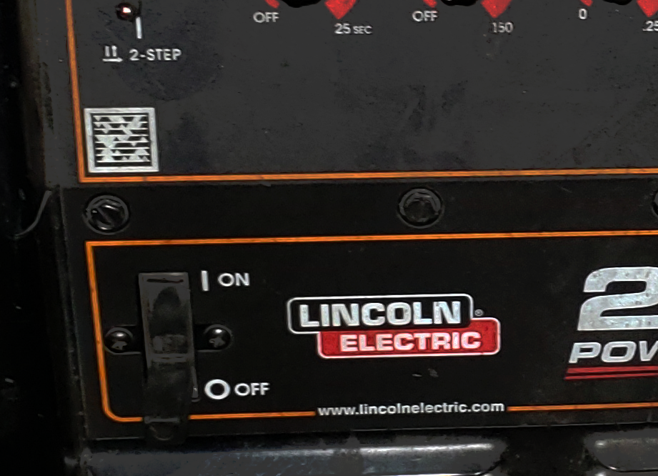
Power Switch - on/off switch
-
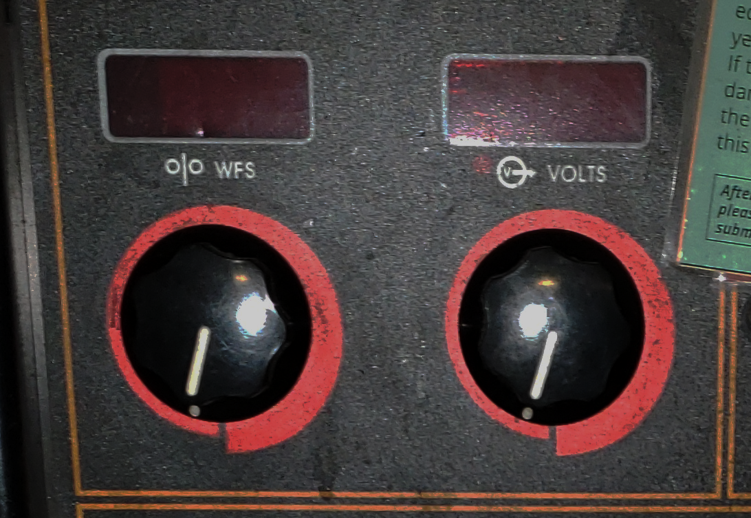
Wire feed speed - This controls how fast the wire is fed through the MIG gun. The faster the wire is fed, the more material will be deposited into the weld puddle, and the more current/amperage will be pushed through the circuit. The higher the amperage, the more heat will be put into the weld puddle.
-
Volts Knob - The voltage is set by the operator, and then during welding, the power supply adjusts the current being fed through the arc in order to maintain the desired voltage. Generally, a higher voltage will produce a wider puddle, and a lower voltage will produce a narrower puddle.
-
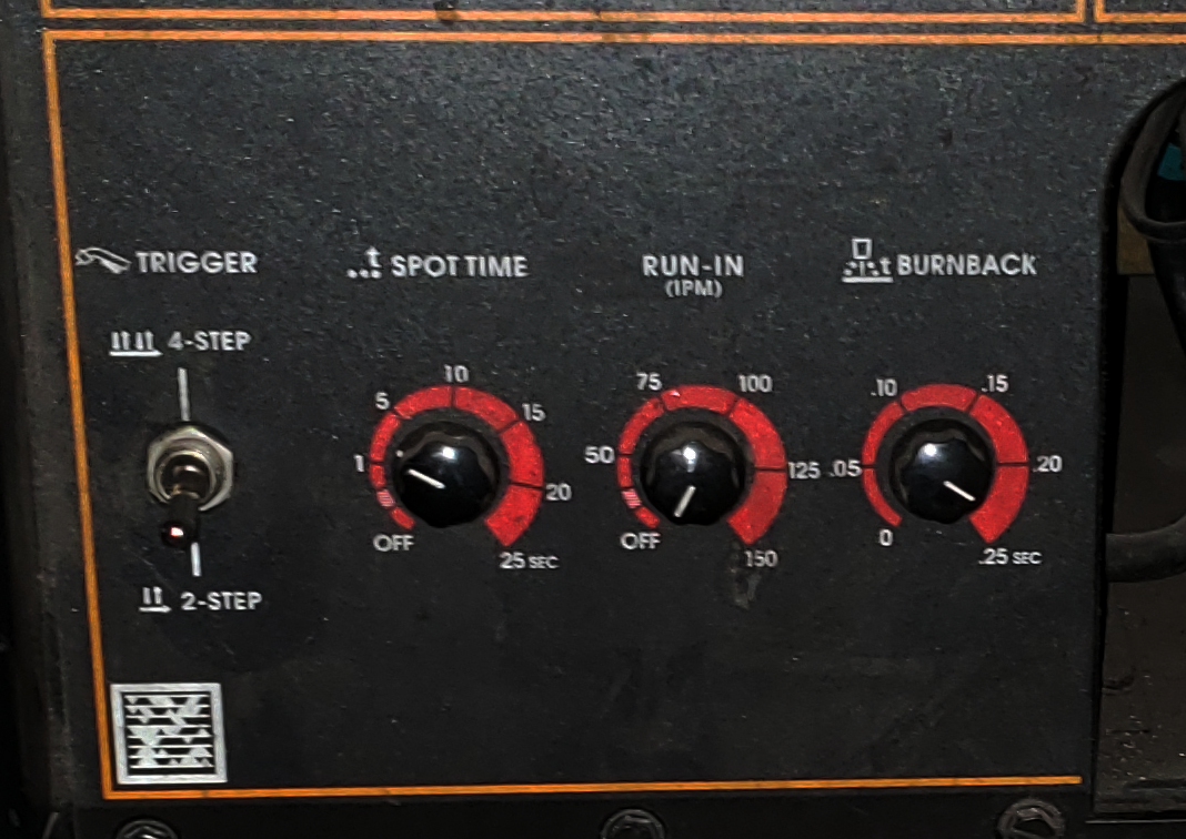
Trigger Mode - Leave this at ‘2-step’, as it can cause a dangerous situation for the next user if they are not notice the setting. To reduce fatigue in high-production situations it is possible to set the welder to ‘4-step’ and the welder will continue feeding energized wire after releasing the trigger. To stop the welder, the trigger must be depressed and released a second time.
-
Spot time - Provides a timed power pulse in order to create uniform tacks. Power will be cut off after a specified time while keeping the trigger depressed. Generally this is left ‘off’.
-
Run-in - Allows a slower wire feed to be used until the arc is initiated, which can help when starting a weld using difficult materials like stainless steel. Generally this is left ‘off’.
-
Burnback - Controls how long power will be applied after the trigger is released and the wire feed is stopped. This will cause the electrode wire to burn back towards the mig gun, effectively retracting it from the weld puddle before it cools. Too much burnback will cause the wire to fuse itself to the contact tip.
-
Cover - Everything inside the cover should be considered energized when the welder is turned on, so the cover should always be closed unless the machine is unplugged.
-
Wire Spool - The wire pushed out of the gun is stored on a spool inside the welder. You should verify that there is sufficient wire remaining for your project before starting.
-
Feed Rollers - The feed rollers push the wire through the lead to the welding gun. They must match the size of the wire being used.
-
Feed Roller Tensioner - This spring-loaded knob applies the proper amount of pressure to the feed rollers to allow them to push the filler wire without crushing it. It can be pulled to the left to unlock the arm holding the top feed roller.
-
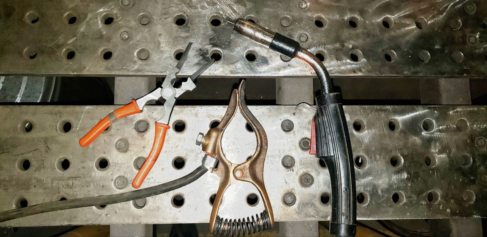
MIG Pliers - These specialized pliers have specialized features that allow you to perform frequently needed maintenance on the mig gun, like clip the filler wire to length, clean out spatter from the nozzle, and unscrew the contact tip. They are also quite useful when moving hot metal pieces around the bench.
-
Ground Clamp - Sometimes referred to as the Work Clamp, this clamp is attached to the workpiece in order to complete the circuit from the electrode back to the welder. This must have good electrical contact with the workpiece in order to achieve a solid arc. Clamp directly to a bare metal part of the workpiece, since clamping this to the table will force the electrical current to jump from the workpiece to the table, and the workpiece will tend to weld itself to the table. Paint and rust will block the current from flowing.
-
MIG Gun - Acts as the second electrode in the welding circuit, and ejects filler wire into the weld.
-
Gun Trigger - When depressed, the shielding gas will begin to flow, wire will begin to feed at the set speed, and power will be supplied to the contact tip at the configured voltage.
-
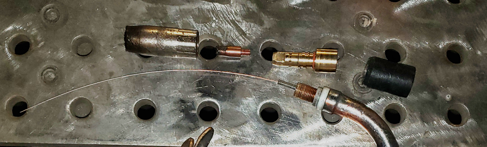
Gas Diffuser - The heart of the MIG gun, the diffuser holds together the gun, contact tip, and nozzle. It also distributes the shielding gas evenly around the nozzle to provide an even flow from the tip of the gun.
-
Contact Tip - The tip at the end of the gun must have an electrode tip that matches the size of the wire. This electrode will wear out over time and should be replaced when damaged. The wire will sometimes weld itself to the tip when there is extreme burnback or spatter. Often the wire can be freed from the tip using pliers.
-
Gas Nozzle - This helps direct the shielding gas over the contact tip and flood the weld area. Weld spatter can build up on and inside the nozzle causing flow issues. Clean the nozzle periodically to ensure good gas flow.
-
Insulator Sleeve - Provides an insulating barrier between the wire electrode and the rest of the welding gun so the user does not get shocked.
-
Maintenance Tag - Manually tracks the usability status with Green/Yellow/Red cards
Tool Safety
COMMON HAZARDS
Common hazards include electrocution, hot surfaces, sparks, UV light exposure, and toxic gasses.
To avoid electrocution, never open the side case without unplugging the machine. When operating the welder, make sure that the workpiece is properly grounded with the ground clamp, and that no part of your body is introduced into the circuit between the gun electrode and the workpiece. I.e. do not hold the wire against your hand and pull the trigger. Take care to maintain control over any filler wire that is ejected from the gun while purging the gas lines to prevent incidental contact with any person or nearby objects.
When working in the welding area, assume that any metal objects or surfaces are hot. A previous worker may have set down a hot piece of metal and walked away. Hover your hand over any piece to see if it is radiating heat before touching it. Use gloves and pliers as appropriate to move hot pieces.
Wear thick, natural-fiber clothing to keep sparks from contacting your skin.
UV light is especially harmful to your eyes, but can also cause damage to any exposed skin. Always wear a welding helmet with a shade of at least 10, and cover all skin surfaces.
Make sure your workpiece is completely cleaned of any paints or coatings. Heat will travel quite a distance through the workpiece, so you must strip far more than just where you will be welding. Always position the fume hood where it can capture the welding fumes.
PROHIBITED MATERIALS
Workpieces that are painted, powdercoated, galvanized, or otherwise similarly coated should not be welded. Many solvents, especially those containing chlorine, are prohibited. If at all in doubt, use acetone and allow it to completely evaporate before welding. Toxic fumes can kill you and others nearby.
Initial Setup
Prepare your weld fitment
This is one of the most critical and time-consuming parts of the welding process. The parts to be welded must be ground down to bare, shiny metal, and be free of oils and debris.
A flap disc, grinder, or wire wheel is often used for this purpose. A flat, undamaged work-surface is necessary for precision fitups, so do not grind on the welding table without taking steps to protect the table from incidental grinder contact if you must grind in the welding area. The pieces should fit together snugly; it is possible to fill in gaps with weld, but it is less-than-ideal. When joining material thicker than ¼”, the edges will likely need to be beveled in order to achieve a deep, strong weld.
Grinding wheels and wire brushes dedicated to aluminum should not be used to clean steel. Small bits of the steel will become embedded in the wheel or brush, and will contaminate any aluminum it is used on in the future.
Secure your workpieces
Immobilize your work using clamps, magnets, or other fixturing devices. Give enough room between your weld area and the fixtures to prevent damaging them while welding.
Put on your PPE
Find a welding helmet and adjust the head band so it fits securely on your head. Double-check to make sure the shade level is 10 or higher, and grind mode is not activated. Wear safety glasses under your hood. Make sure you cover all skin surfaces by wearing MIG gloves, a welding jacket, long pants, and shoes made of natural fibers (leather boots preferred).
Position the workspace protection
Make sure the welding curtains block all possible line-of-sight from the arc to other parts of the shop. Other users of the shop may not be aware that the welding arc may damage their vision.
Position the fume extractor above or next to where you will be welding. You should move this frequently for maximum effectiveness as your welding position changes.
Open the gas tank
Make sure the regulator knob is backed off so there is no tension on the spring. Do not unscrew it so far that the knob comes out of the regulator.
Very slowly open the tank valve. In rare instances the valve itself has been blown off of the top of the tank while being opened. Do not place your hand on top of the valve handle to avoid serious injury if this were to occur. Opening the tank valve too quickly can shock the regulator, rupturing the diaphram and throwing debris at the operator. Stand to the side of the regulator so as to be out of the most likely path of debris if the regulator were to rupture. Once the tank pressure needle begins to move, stop opening the valve and allow the regulator to pressurize. The right gauge should read somewhere between 100 and 2000 psi. If the gas is low, please submit a maintenance request to swap the tanks. Once the regulator has pressurized, open the valve at least two turns to allow proper gas flow.
Once the tank valve has been opened, slowly screw in the regulator knob until the desired working pressure on the left gauge has been achieved. Note that the pressure may drop slightly while shielding gas is actively being dispensed by the welder. Adjust the regulator so that the proper shielding gas coverage will be achieved while actually welding. A common setting for MIG welding is 18cfh. Please be conservative with your setting, and only use as much flow as is needed to get adequate coverage.
Turn on the welder and adjust the settings
Turn the power switch to “ON”. Using the chart of established settings found on the welder’s case, determine the proper wire feed and voltage and adjust the machine appropriately.
Check that the trigger mode is in “2-step”.
Turn off the spot time and run-in unless needed.
Set your burnback to .15 seconds.
COMMON SETTINGS
Voltage/Feed/Wire diameter chart for 75% Ar / 25% CO2 mix
CONSUMABLES
The shop is responsible for providing all consumables for the MIG welder, but you will need to know when they need to be replaced.
The contact tip should not have any looseness between the orifice and the filler wire. If the wire can be wiggled back and forth in the contact tip, the tip should be replaced.
The nozzle should be free of spatter and debris. Coating it with anti-spatter will help keep it clean. If it is partially clogged, use the MIG pliers to clean it out. If the spatter is too well fused to the nozzle to clean out, it must be replaced.
The spool of filler wire will need to be replaced when it has been exhausted.
Basic Operation
Trim the wire
Before you weld, you should trim off any excess wire at the end of the gun, establishing your stickout at about ¼”.
Check your position
Before welding, you should check to make sure that you have free and smooth access to the weld joint along it’s entire length. Making a dry run will often bring interference and entanglement issues to your attention.
When you are ready to weld, place the tip of the nozzle about ¼” away from the joint. The gun should be pointed directly away from the weld (i.e. straight up in the air if welding on a flat surface) and tilted 10 degrees in the direction of travel. The tip of the wire should not be touching the workpiece when you pull the trigger, but should instead be power-fed into the workpiece.
Lower your hood
With a quick nod of your head, drop the hood over your face.
Announce “Welding”
Ensure that anyone in the area knows that you are about to initiate an arc by announcing that you are “Welding”. This gives them time to avert their eyes if they are unprepared.
Tack
Make a small tack weld at the start and end of the weld joint you are about to make. This prevents the pieces from shifting or drifting apart during the weld due to heat movement. You should inspect these welds and clean off any soot before continuing.
Weld
Once the parts are tacked in place, initiate the arc at one end of the joint and, keeping your perpendicular position with a 10 degree angle towards the direction of travel, keep the filler wire feeding into the weld puddle at the leading edge of the molten pool.
The speed with which you move will determine how much ‘build up’ the weld profile will have. The faster you go the lower the bead will be, and the slower you go, the more metal will be deposited along the length of the weld.
In many operations, you will find that some amount of ‘weaving’ back and forth across the joint will be needed to tie the weld securely into the material on both sides of the weld. This is often described as drawing a series of “U” shapes, or lowercase cursive “e”s.
Terminate
When you reach the end of the weld joint, pause briefly to add a bit of additional fill at the end of the weld. Without adding this additional fill, the end of your weld will develop a slight crater in it as the molten puddle cools and shrinks. That crater will be a weak spot in the weld, and may lead to cracking and failure of the joint.
Wait
After extinguishing the arc, pause for a moment and let the puddle cool before continuing. Our MIG machine has no post-flow. Cooling the weld artificially by dunking it in water, etc. will thermally shock the weld and will likely lead to cracking and failure.
Clean the weld and inspect
Look the weld over for signs of porosity, proper fusion at both sides of the weld, and an appropriate bead profile. Use a wire brush to clean off any soot and silicon deposits.
Cleanup
Close tank and purge regulator
Turn the tank valve handle clockwise until it is firmly seated in the closed position.
The residual pressure must be purged from the regulator to prevent damage to the springs and diaphragm. To release the remaining gas in the lines, the gas solenoid must be activated using the gun trigger, which has the unwanted side-effect of feeding wire. In order to minimize the amount of wire ejected from the gun during purging, turn the wire feed down to its lowest setting.
Point the gun in a direction where the extending wire won’t contact any person or objects and pull the trigger. After a few seconds the gas pressure gauges should both drop to zero.
Once the gauges are at zero, turn the pressure regulation knob counter-clockwise until there is no tension being put on the diaphragm by the knob. The knob should not be unscrewed completely from the regulator.
Turn off welder
Flip the power switch to ‘OFF’.
Store the leads
Coil the ground and gun leads loosely and drape them over the handle of the welder.
Making sure the welder is off, either clip off the excess wire from the gun tip, or open the cover, unclamp the feed roller tension handle, and slowly turn the wire spool clockwise to re-spool the few inches of excess wire until it is just barely sticking out at tip of the gun.
Clean up clamps
Gather any clamps, magnets, and fixtures on the welding tables and return them to the tool cart.
Sweep the floor
Use a broom to sweep the entire welding area, collecting any grinding dust, filler wire, and cut-offs that may be on the floor.
Scrap
There is a small scrap bin under the cutting table into which recyclable steel may be placed.
MAINTENANCE REQUESTS
-
Update the physical Maintenance Tag at the machine
-
Green can be used without issue
-
Yellow can be used with caution
-
Red cannot be used without hazard to either the user or the equipment
-
Record issues at protohaven.org/maintenance. This notifies our staff and volunteer maintenance crew of any issues
Troubleshooting
Additional Resources
Eastwood’s Intro to Mig Welding - https://www.youtube.com/watch?v=W4-eYXsUr3g
Staff-Use
AUTHORIZED MAINTENANCE CREW ONLY
If you are part of the maintenance group please log on to the #maintenance channel of our Discord server to:
-
Perform a Maintenance Action
-
Request a Maintenance Purchase
-
Review complete Maintenance Logs for each machine
-
Generally chit-chat about maintenance
What preventative maintenance areas does the manual indicate? For example, a regular oil schedule, how often to tension belts/blades, and when to change a filter.
This is the area to simply name the topic, frequency, and page number where more information can be found in the manual.
Links to helpful videos or additional resources would be a helpful secondary source.