Welding & Plasma Cutting - CNC Plasma Cutter
Hypertherm Powermax65 with CNC Router Parts PRO CNC Plasma Kit
Clearance: Required
Filling and Draining the Plasma Table
Filling and Draining the Plasma Table
The plasma table is made from aluminum and has steel slats that the material to be cut material rests on. Primarily, steel is the most common material that is cut. When steel and aluminum are in contact, a galvanic reaction occurs and aluminum is usually the loser in that reaction. We have begun running an additive in the table that will slow this reaction but in the name of belt and suspenders, we are draining the water from the table. This will not stop the reaction completely but should considerably slow it.
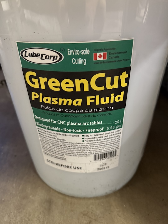
The additive we are running is Green Cut Plasma Fluid at a 20:1 ratio. This may leave a film on plasma cut parts.
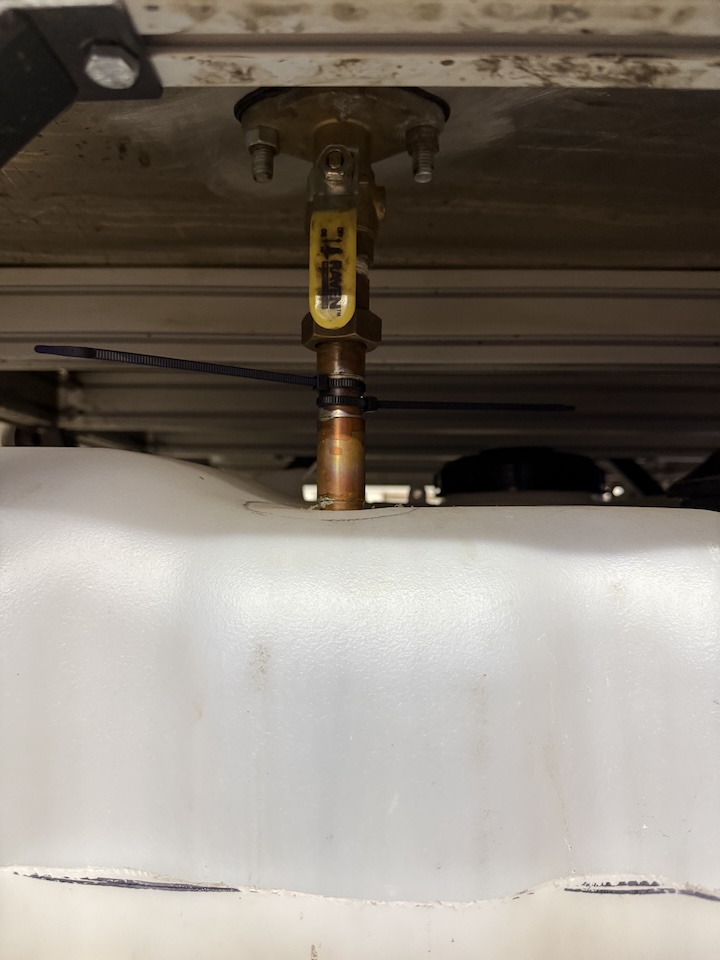
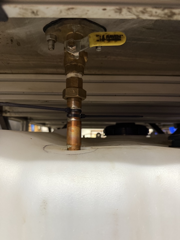
When you first approach the table, it will be drained into the lower holding tank and the drain valve will be open (vertical position). Move the valve to the horizontal position to close it. The valve can be found by looking under the table, at the front.
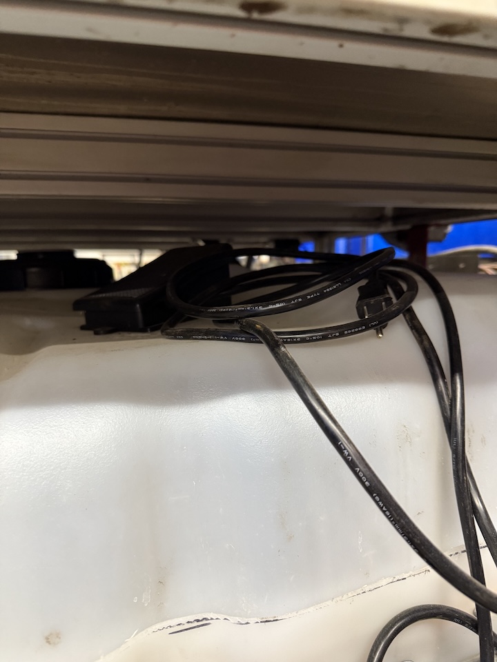
Next, locate the foot switch for the pump. It should be stored on top of the tank. At the front, on the right. Plug the foot switch onto the an outlet under the computer. Depressing the pedal once and releasing will activate the pump. Pressing and releasing a second time will turn the pump off.
The fluid will come out of the rear outlet and fill the table in about 6 minutes. Use this time to prepare your files for plasma cutting.
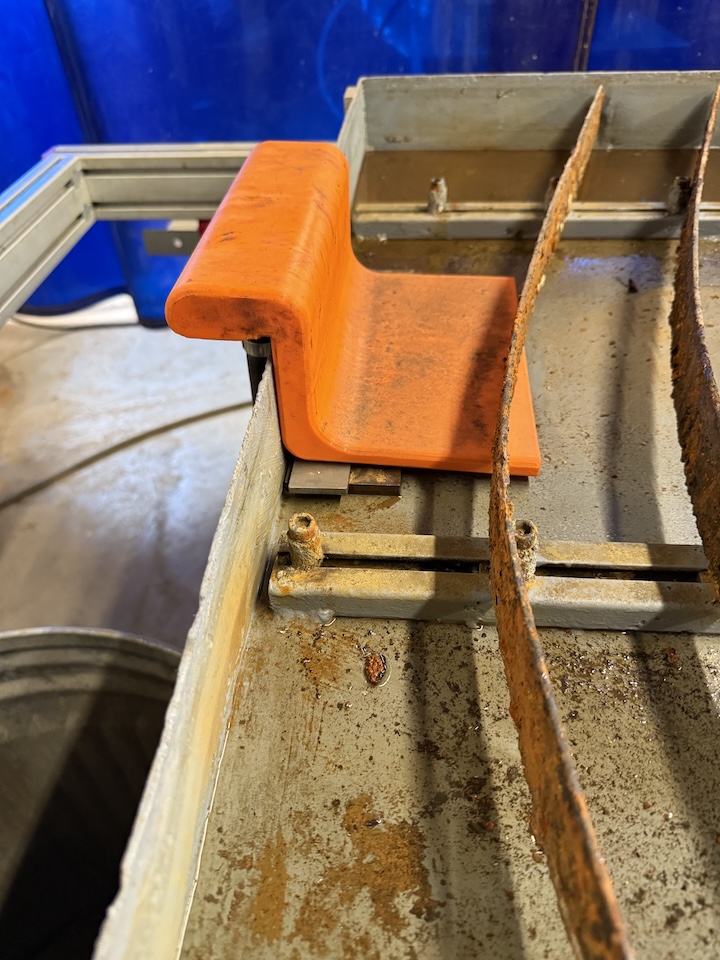
Allow the table to fill till the slats at the front are about 1/8" from being submerged. Then switch the pump off, unplug the switch and put it away. There is an overflow fitting at the rear of the table, it should be impossible to overfill the table but please refrain from testing this too much.
When done plasma cutting, move the drain valve to the vertical positionopen to drain the table, allowing the water back into the tank. Please clean up any large debris that is left from your use of the machine.
Maintenance notes:
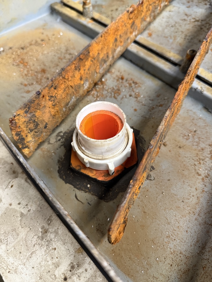
The orange fittings are 3d printed and the 3d print files are here:
The Water supply is best printed on its side. It also needs to rest on the couple pieces of metal, because it will wick fluid up behind it and onto the floor. If a replacement needs to be made, feel free to experiment with redesigning to prevent wicking. I suggest opening up the tolerances where it slips over the table.
https://wiki.protohaven.org/attachments/303
The bulkhead fitting is printed with reverse threads to counteract the rotation of the earth and moon..... (joking). Just be aware when trying to assemble and disassemble. The washer is printed from TPU, a sealant should be used to get a better seal of these parts.
https://wiki.protohaven.org/attachments/304
The white fitting on the bulkhead fitting is a 1.5" sink tail piece extension that is cut to length, this was done as a consumable that is inexpensive and easy to replace in the event of damage.
Green Cut Plasma Fluid:
This is mixed at a 20:1 ratio and is checked via PH. The reoccurring CNC Plasma 14 Maintenance covers the check. Typically the water is consumed and needs to be replenished.
A refractometer may be a good future purchase to check the exact concentration levels.
A filter system is suggested by the Green Cut Plasma Fluid company. We are currently not filtering out fluid beyond letting it settle out in the tank.
Manual(s)
Manuals and other reference materials from the manufacturer or other sources.
-
Avid Pro
-
Mach3
-
Hypertherm
Member Notes
Fusion Plasma Post Processer protohaven mach3 plasma.cps
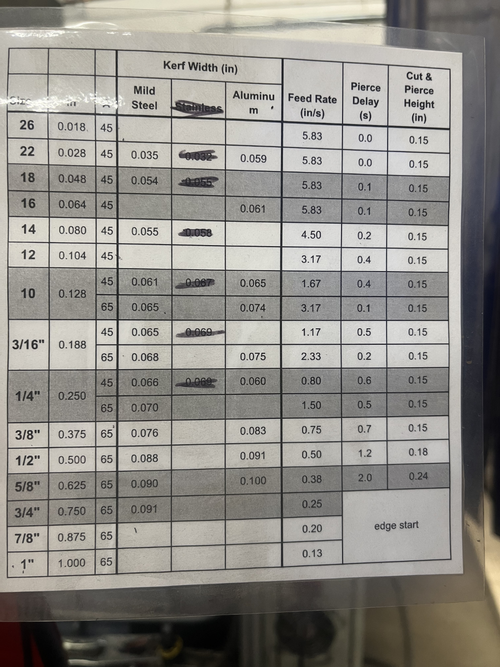
Speeds and Feeds as of 3/3/2026
Resources
Where to obtain materials, consumables, and tooling.
Tool Tutorial
CNC Plasma Cutter (Avid Pro)
The Avid Pro Plasma 4x8 CNC system plus Hypertherm PowerMax 65 plasma cutter can run cutting operations on sheet metal including mild steel, and aluminum.
Quick Facts
- Max cut size 1“ (at 65A)
-
Members need to supply their own plasma consumables - these are available for purchase at the front desk.
-
Do NOT cut stainless steel on this machine - hot metal operations on stainless steel can produce hexavalent chromium, which is highly carcinogenic.
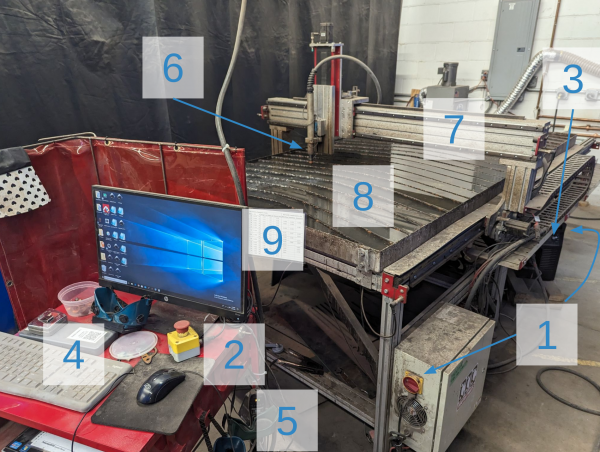
Tool Anatomy
-
Power switches (motor & plasma cutter)
-
E-Stop
-
Amperage control (45A/65A)
-
Control Computer
-
Welding Goggles
-
Torch Head
-
Gantry
-
Water Table
-
Speeds & Feeds Chart
Initial Setup: Powering On
It's strongly recommended to reserve a timeslot so you know the machine is available.
-
Top up the water in the water table if there's >5mm of open space to the top of the slats
-
Roll the trash bin by the plasma over to the sink, fill it, return to CNC plasma, and slowly pour water in the center of the water table using the included bucket.
-
-
Ensure a good nozzle and electrode are loaded in the torch head
-
Disconnect the THC wire and unscrew the head
-
Verify the amperage rating of the nozzle (45A or 65A printed on the side)
-
Replace electrode and/or nozzle if the wear pattern is not symmetric
-
Screw down the head until it gently stops, then reattach THC wire
-
-
Turn on the Hypertherm and ensure its amperage setting matches the nozzle rating
-
Turn on the control box and use Mach3 to move the head free of your work area
-
Load your material and attach the ground clamp nearby
-
Draw the curtain behind you to protect other members from arc flash
Preparing G-Code: SheetCam
-
Create/edit an existing tool for Material Type & Thickness by referencing the Hypertherm Torch Operator Manuall to your Material Type & Thickness:
-
Feed Rate
-
Pierce Delay
-
Pierce Height
-
Cut Height
-
Import your plasma .DXF file as “new part”
-
Select your part
-
Create new “Plasma Cut” Operation (Operation>Plasma Cut)
-
Select the layer that contains the vectors you want to cut
-
Choose Contour Method
-
Outside Offset is typical for jobs with a mix of closed/open profiles
-
Enter the feed rate based on your material type and thickness
-
Configure lead-in and lead-out settings and press OK
-
Verify that the cutting preview shows the appropriate direction & leads
-
To prevent the cutter from crashing into parts that flip up during operation, go to Options → Job Options and ensure the Rapid Clearance field is set to 3” or larger (a higher value takes longer to touch off when starting a cut, but is less likely to crash on already cut pieces)
-
Run the Post Processor to create your .TAP g-code file
Import Scaling Issues
Occasionally, importing .svg parts from Inkscape creates non 1:1 scaling. If this occurs, the following usually works:
- Set inkscape part dimensions in inches with hariline line width
- Save the document as a DXF R12 *.dxf file to the document
- In SheetCAM, click file in the upper left-hand corner and select "Import Drawing"
- Select custom scaling and set 1:1 scaling
Operation: Mach 3
-
Hit flashing red “Reset” button to clear Emergency Stop condition
-
If the button does not reset when clicked, check that E-Stops & Proximity Limit Switches are unlocked
-
Select “Reference All Home” (wait until all three axis lights are green)
-
Zero X, Y, and Z axis
-
Load your file (File>Load G-Code)
-
Jog the machine head to the left/front corner of the desired origin (arrow keys)
-
Before zeroing, make note of the coordinates so that, if you need to restart mid-cut, you’ll have the exact location to return to
-
If prefered, select ”MDI Alt 2” to manually jog to the nearest whole number for your desired origin
-
Zero X and Y on the left/front corner of the desired origin
-
Zero Z with torch approximately ¼” above the material surface (page up/down)
-
Trace the job location using jog/arrow keys to ensure your file fits where desired
-
Safety Check:
-
Identify nearest fire extinguisher
-
Ensure E-Stop is easily accessible
-
Put on appropriate eye protection
-
Select “Cycle Start” to begin cutting
Cleanup
-
Turn off the control box
-
Turn off the plasma cutter (Hypertherm)
-
Remove any remaining material from the table
-
Detach the ground clamp and store it clear of the water table
-
If using your own consumables, remove them from the nozzle and replace them with a spare from the workstation table.
-
If using one, remember to take your flash drive with you!