It's a good idea to save (Ctrl+S) periodically while designing in Inkscape - the program does sometimes crash and any unsaved data can be lost.
1. Using the circle and rectangle toolbar icons on the left side of the window, draw two circles and a rectangle of any size. [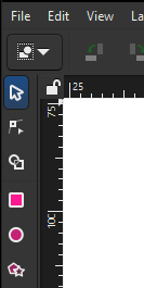](https://wiki.protohaven.org/uploads/images/gallery/2025-02/9gtimage.png)[](https://wiki.protohaven.org/uploads/images/gallery/2025-02/80vimage.png) 2. Select all objects and set the stroke to black, and the fill to transparent (the "X" color on the bottom left corner of the page) [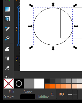](https://wiki.protohaven.org/uploads/images/gallery/2025-02/GBBimage.png) 3. Set the dimensions of the rectangle to 75x15mm and the width/height of each circle to 20mm (i.e. 20mm diameter) For rectangle: 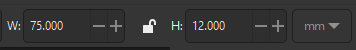 For circles: [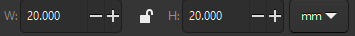](https://wiki.protohaven.org/uploads/images/gallery/2025-02/h0himage.png) 4. Ensure the rectangle and circle stroke style are all set to "hairline" (`Object` > `Fill & Stroke` to open the right panel, then select the `Stroke Style` tab and select "hairline" from the width's units dropdown). [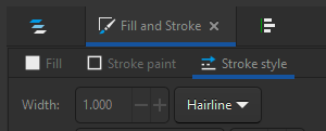](https://wiki.protohaven.org/uploads/images/gallery/2025-02/w55image.png) 5. Drag the circles so they hang over either side off the rectangle. [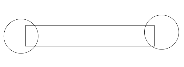](https://wiki.protohaven.org/uploads/images/gallery/2025-02/f2Himage.png) 6. Using the Align and Distribute panel (Accessible from the top menu - Object > Align & Distribute), select all three objects and click "Center on horizontal axis" (the icon in the bottom middle of the Align icon set) to align their vertical centers. [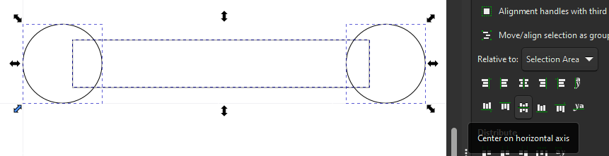](https://wiki.protohaven.org/uploads/images/gallery/2025-02/7ysimage.png) #### Creating the interior/flats 1. Select the star/polygon tool from the left menu bar. The top toolbar will change to offer some options for the tool; ensure it is set to create a regular polygon with 6 corners. [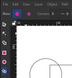](https://wiki.protohaven.org/uploads/images/gallery/2025-02/pTBimage.png) 2. While holding `Ctrl` on your keyboard to snap rotation, draw a hexagon with horizontal top and bottom sides. Press escape a couple times to get back to the selector tool. [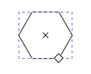](https://wiki.protohaven.org/uploads/images/gallery/2025-02/kjaimage.png) 3. Select the created hexagon, lock the aspect ratio using the padlock icon near the width/height text boxes, and set the height to 10mm. The width should adjust automatically to maintain the shape of the hexagon. [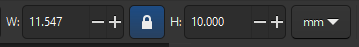](https://wiki.protohaven.org/uploads/images/gallery/2025-02/rcHimage.png) 4. With the hexagon selected, shift-select the left circle. Navigate back to the Align and Distribute panel, then set `Relative to` to `Last selected`. Center on horizontal axis and vertical axis using the two icons on the panel (you can hover over them to see the name of the alignment operation). [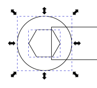](https://wiki.protohaven.org/uploads/images/gallery/2025-02/rLximage.png) 5. Deselect all objects by clicking elsewhere on the page. Select, copy (Ctrl+C) and paste (Ctrl+V) the hexagon near the circle on the right side, then perform the same alignment as in the previous step to align it to the right side circle. You should have something that looks like this: [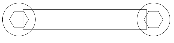](https://wiki.protohaven.org/uploads/images/gallery/2025-02/Rtyimage.png) 6. Select the left hexagon and convert it from a hexagon to a path via `Path` > `Object to Path`. Confirm you now have a path selected by looking for "Path 6 nodes in layer..." at the bottom of the window.[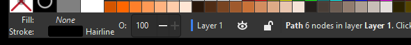](https://wiki.protohaven.org/uploads/images/gallery/2025-02/WPpimage.png) 7. Double click the already-highlighted hexagon (or click the Node Tool in the left toolbar). The hexagon will now show drag handles on each of its corners. [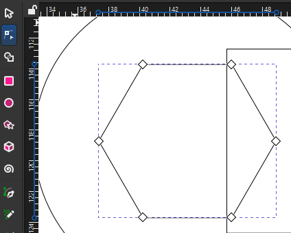](https://wiki.protohaven.org/uploads/images/gallery/2025-02/ZVMimage.png) 8. Drag- or shift-select the left three nodes. While holding Ctrl to constrain movement, Click and drag the nodes until they lie outside the left side of the circle. [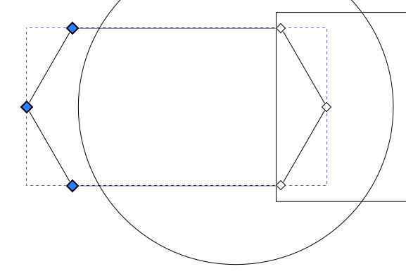](https://wiki.protohaven.org/uploads/images/gallery/2025-02/5iiimage.png) 9. Press the Escape key a few times until the UI stops changing - nothing should be selected, and you should have the Selector Tool highlighted in the left toolbar. #### Using Shape Builder to create the final design 1. Press Ctrl+A to select all objects, then click the Shape Builder tool on the left toolbar. Your design should now be filled in gray and you should see "Add", "Delete", and "Finish" icons in the top toolbar. [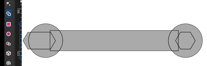](https://wiki.protohaven.org/uploads/images/gallery/2025-02/wdiimage.png) 2. With the "Delete" icon selected, click on all of the parts of the wrench we do not want in the finished product. These will disappear from the page: [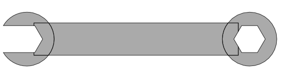](https://wiki.protohaven.org/uploads/images/gallery/2025-02/dEsimage.png) 3. Now click on the Add icon in the top menu bar, then **click and drag** on all parts of the wrench to preserve. These will highlight in blue, and any edge you drag over will be eliminated: [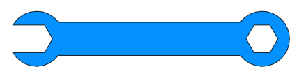](https://wiki.protohaven.org/uploads/images/gallery/2025-02/9riimage.png) 4. Press the checkmark "Accept" icon next to the Finish label on the top menu bar to lock in your changes. Congratulations, you've made a wrench!You can compare your work against this reference file: [wrench.svg](https://wiki.protohaven.org/attachments/219)
# 3D (Fusion 360) Design: Wrench Holder This simple tutorial walks you through designing a 10mm "box" wrench holder with accurate dimensions. You can modify the shapes in this tutorial to quickly create other designs which can then be created using Protohaven's 3D printers, Tormach CNC mill, and other tools that operate with STL or 3D design files.This tutorial is part of the [2D & 3D Design Bootcamp](https://docs.google.com/presentation/d/1nUnqCCwc6WJTSujynFp_blcZtKtCzdi3Rts6wXkXLko/edit?usp=sharing), and relies on the file from [2D (Inkscape) Design: Basic Wrench](https://wiki.protohaven.org/books/class-handouts/page/2d-inkscape-design-basic-wrench "2D (Inkscape) Design: Basic Wrench"). If you'd rather start with this tutorial, be sure to download [wrench.svg](https://wiki.protohaven.org/attachments/220) so you can use it in the steps below.
Fusion 360 requires a (free) license to operate - if you don't have a license already, go [here](https://wiki.protohaven.org/protohaven.org/f360/signup) to obtain one.
#### Setting up the main body 1. With Fusion 360 open to a new project, click on the "Create Sketch" tool in the top menu (under SOLID), then click on the bottom (XY) plane. [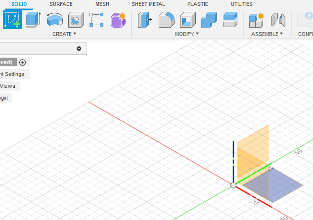](https://wiki.protohaven.org/uploads/images/gallery/2025-02/H14image.png) 2. The view will change to a top-down view. click to expand the CREATE top toolbar menu, then navigate to Rectangle > Center Rectangle. Click the origin on the 3D view, then move your mouse and click again to create a rectangle centered on the origin. [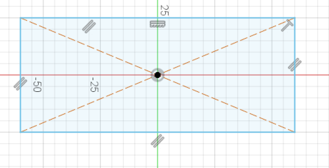](https://wiki.protohaven.org/uploads/images/gallery/2025-02/XRYimage.png) 3. Expand CREATE again to select Sketch Dimension (or press the D key as a shortcut). Click the top edge of the rectangle, then move your mouse upwards a bit and click again to place the dimension. Type "120 mm" into the value box and hit Enter to set the dimension. [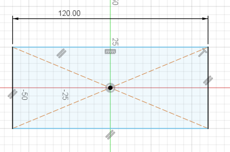](https://wiki.protohaven.org/uploads/images/gallery/2025-02/eRIimage.png) 4. Use Sketch Dimension again, this time on the left edge of the rectangle. Make this dimension 60mm. Press escape on your keyboard to exit the Sketch Dimension tool. [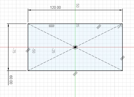](https://wiki.protohaven.org/uploads/images/gallery/2025-02/vt4image.png) 5. At this point, the whole rectangle should be black. Clicking and dragging any part of the rectangle (other than the dimensions) should do nothing. This is called being **fully constrained**. Designing parts that are fully constrained is recommended when doing any kind of complex design work, as it saves time when adjusting things later. 6. Click the green "FINISH SKETCH" checkmark on the top right of the screen to finish the sketch. The view should change to an isomorphic (corner) view of your rectangle. 7. Click the "Extrude" tool in the top toolbar, then click on the interior of the rectangle. Enter -20mm, then press Enter to extrude a solid body downwards from the rectangle. [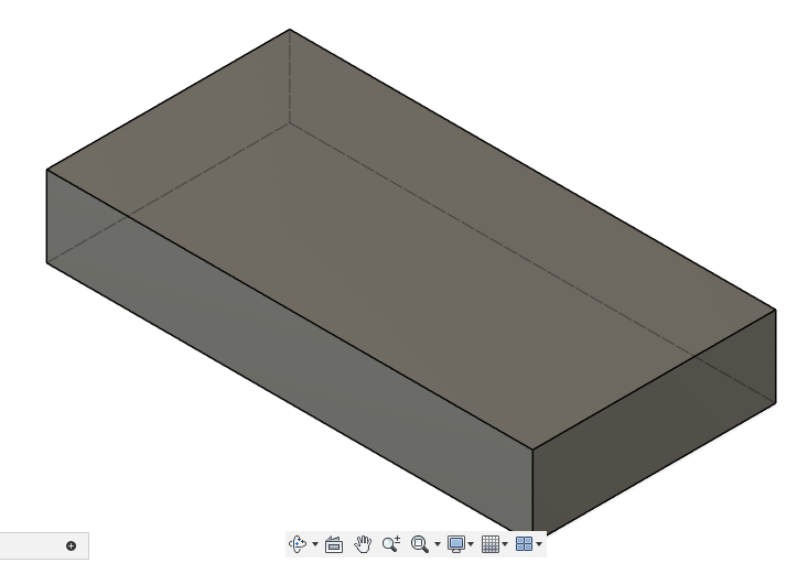](https://wiki.protohaven.org/uploads/images/gallery/2025-02/Zmjimage.png)Now that we have a few operations, take a look at the timeline on the bottom of the application window. You can go back and edit any sketch or feature by double-clicking on one of the icons in the timeline.
[](https://wiki.protohaven.org/uploads/images/gallery/2025-02/8h9image.png) #### Creating the wrench caddy 1. Expand the "INSERT" menu on the top toolbar and select `Insert SVG`, then `Insert from my computer`. Navigate to the [wrench.svg](https://wiki.protohaven.org/attachments/220) file and open it, then click on the XY plane (as with the first step when creating the rectangle sketch). The wrench will appear, but it won't be the right size or in the right place. This is because SVG describes a **Scalable Vector Graphic which does not usually include units (e.g. mm or inch) in the file data. [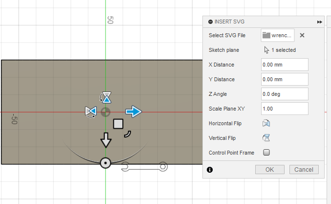](https://wiki.protohaven.org/uploads/images/gallery/2025-02/CSNimage.png) 2. Set Scale Plane XY to 2.54 to convert from cm to inches, then drag the wrench so it's on the top half of the rectangle. Click OK. [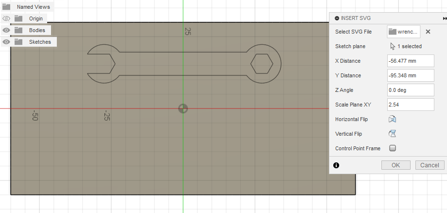](https://wiki.protohaven.org/uploads/images/gallery/2025-02/U03image.png) 3. Under the MODIFY top toolbar menu, click on Offset, then click the outer perimeter of your wrench. set distance to 1mm, then click OK to add a 1mm offset around the existing design. This prevents our wrench from being exactly the same size as our wrench slot, which would produce a "press fit" that makes our wrench difficult to remove and use. [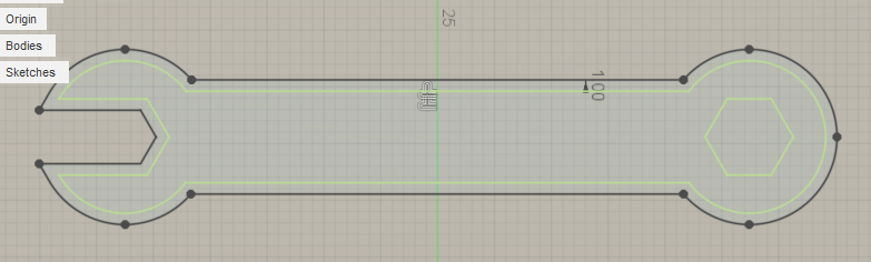](https://wiki.protohaven.org/uploads/images/gallery/2025-02/niPimage.png) 4. Click FINISH SKETCH to exit the sketch, then enter the Extrude feature tool just like we did before. 5. Left click within the area of the wrench sketch, the as well as the main body of the wrench and the closed hexagon side. Type **-3mm** to extrude it downwards into the rectangle body. Fusion 360 will automatically perform a Cut operation to remove this material. Click OK to complete the operation. [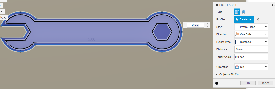](https://wiki.protohaven.org/uploads/images/gallery/2025-02/LH6image.png) #### Adding machine screw and nut trays Let's use some solid bodies to make trays for some nuts and bolts we can use with the wrench. 1. Under the CREATE menu of the top bar, select "Box", then click on the top face of the rectangular solid we've been working on. 2. Click nearby the bottom left corner, then click close to the origin to set the second point of the box. Click and drag the middle arrow that appears, until it's pointing 10mm down into the solid body. Click "OK" on the right-side popup menu to complete the operation. [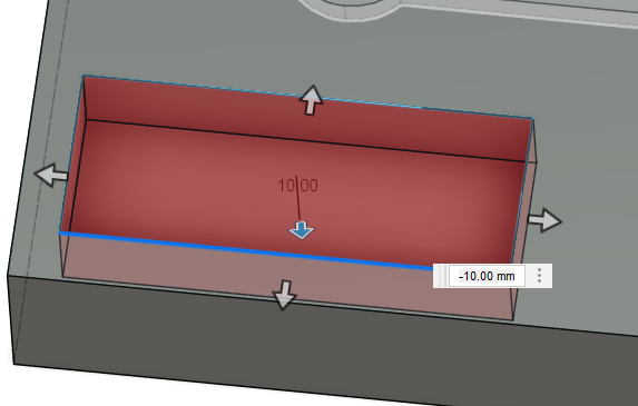](https://wiki.protohaven.org/uploads/images/gallery/2025-02/oJKimage.png) 3. Repeat these steps two more times, but now using the Cylinder tool under the CREATE menu to create 20mm diameter cylinders that cut 10mm into the part. If you need to get a better look at what you're doing, you can orbit around your part by left clicking and dragging the axis cube with X/Y/Z/FRONT/TOP etc. markings on the top right of the screen. [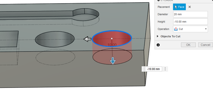](https://wiki.protohaven.org/uploads/images/gallery/2025-02/DVYimage.png) 4. You should now have a wrench tray and a couple bins for nuts and bolts! [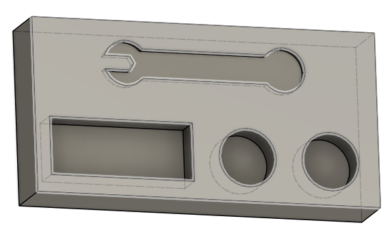](https://wiki.protohaven.org/uploads/images/gallery/2025-02/vFwimage.png)Using primitives instead of sketch/extrude is fast, but you may find it hard to precisely align the features. If you need a primitive exactly positioned somewhere, one way is to create a sketch *before* creating the primitive, and clicking during creation to reference it to a fully constrained point on the sketch. However, this does somewhat eliminate the benefits of using primitive solids vs just creating a fully constrained sketch and extruding it.
#### Rounding corners & finishing details Let's knock off some of the sharp edges on our part to make it nice to handle. 1. Under MODIFY, click on the Fillet tool. Orbit the view around your part and click to select each of the four vertical corners of the rectangle. Set the fillet dimension to 10mm, then click OK. [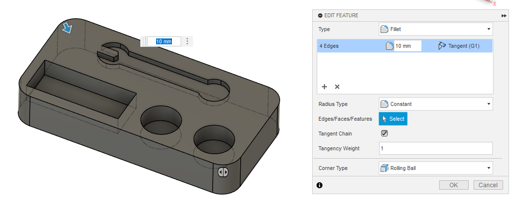](https://wiki.protohaven.org/uploads/images/gallery/2025-02/uIdimage.png) 2. Do this again to create a 5mm fillet on the interior edges of the rectangular tray on the front left side of the part. If you have trouble selecting individual edges, click and hold over the edge to open a menu that allows you to "select through" the body of the part. [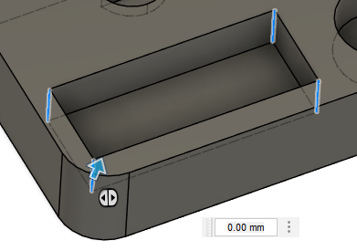](https://wiki.protohaven.org/uploads/images/gallery/2025-02/IBRimage.png) 3. Create a new sketch on the front face of the part, using the Text tool (under the CREATE menu) to place some custom text. Select center alignment, 10mm Arial Bold for the font, and write "10mm" for the text content.[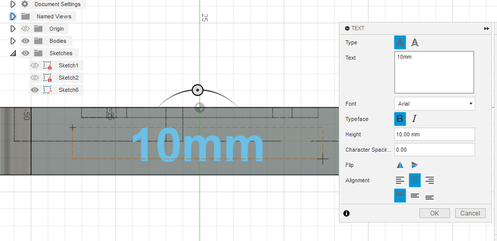](https://wiki.protohaven.org/uploads/images/gallery/2025-02/U6jimage.png) 4. Press OK, then FINISH SKETCH, then select the text and Extrude it 1mm away from the front surface of the part. You should now have a finished wrench and nut/bolt holder! [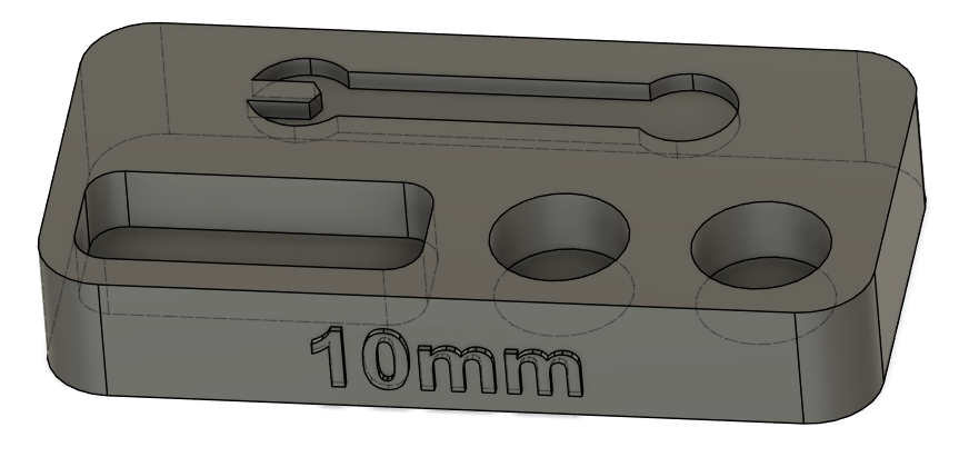](https://wiki.protohaven.org/uploads/images/gallery/2025-02/TVZimage.png) #### Exporting to STL file 1. Expand the Bodies folder in the browser overlay, then right click on Body 1 and select Save as Mesh [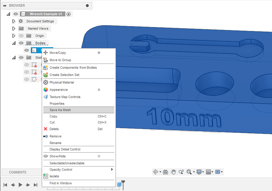](https://wiki.protohaven.org/uploads/images/gallery/2025-02/IHEimage.png) 2. Under Format, select STL (Binary), then click OK and choose where to save your file. You should end up with something like [Body1.stl](https://wiki.protohaven.org/attachments/221) saved onto your computer. # Tormach # Example Step Files Dice: - [Dice.step](https://wiki.protohaven.org/attachments/338) # Fusion 360 CAM Handout # Step-by-step: Facing → Profile → Spot Drill (Fusion 360) --- ## Preparations (before creating operations) 1. Open your design in **Fusion 360** and switch to **Manufacture**. 2. Confirm units (mm or in) — set to what your CNC expects. 3. Save the file (version your CAM changes if needed). 4. Quick checklist: material selected, correct model orientation, correct stock size, tooling on hand. --- Part of learning to be a machinist is understanding how to use a given tool to perform a given job on a given material. This is a lot of variables: we want to be careful with out setup to make sure that making our part is successful. Make sure you understand the tool, and how the tool will help or hinder making your part: - Limitations (speeds and feeds, torque, strength) - Tolerances (precision, runout, flex) Understand your material: what are the general properties of the material, how the material behaves at different speeds and feeds, how the material reacts to various tooling. Knowing the characteristics of your tools and materials will help you design the job that makes your part. ## 1. Create a Setup 1. **Manufacture → Setup → New Setup**. 2. **Operation Type:** Milling. 3. **Model:** Confirm the body/component you will machine is selected. 4. **Work Coordinate System (WCS / Origin):** - Choose a logical origin — commonly top-front-left corner, or bottom (z zero on top of parallels). 5. **Stock:** - Mode: **From solid** or **Fixed size box** (e.g., measure the size of the material stock the part is going to be milled from). - Confirm orientation matches how the part will sit on the machine. 6. Click **OK**. --- ## 2. Facing Operation (2D Adaptive / 2D Face) > Goal: remove top material to create a clean, flat face and establish final Z height. **A. Choose Operation** 1. **2D → 2D Face** **B. Tool Selection** 1. Click **Tool** → **Select**. Pick a face cutter or flat endmill (example: 1/4" flat endmill). 2. Example starting values (adjust to your machine/tool/material): - **Spindle speed:** 8,000–10,000 RPM for aluminum with carbide; lower for steel. (These numbers vary depending on the quality of end mills that are being used) - **Feedrate:** ~30–60 ipm for 1/4" endmillFor the class, use a spindle speed of 8,000–10,000 RPM.
**C. Heights & Passes** 1. **Heights tab:** Set **Top Height** to stock top (usually Stock top). Set **Bottom Height** to final face Z (usually model top). 2. **Passes:** Step-over ~20–50% of tool diameter for finishing; step-down small if face is shallow. If heavy stock, use multiple passes or Adaptive clearing first. **E. Generate & Simulate** 1. Click **Generate**. 2. **Actions → Simulate**. Watch for gouging or collisions. Use **Stock** visualization to confirm material removal. 3. If safe, proceed. If not, adjust heights/clearance or origin. --- ## 3. Profile Cut (2D Contour) > Goal: cut the outside profile (or an interior profile) to final shape or rough to near-net. **A. Choose Operation** 1. **2D → 2D Contour**. **B. Select Geometry** 1. Select the face or sketch edge(s) that define the contour to cut. 2. Pay attention whether you want **Outside**, **Inside**, or **On path.** *This choice affects where the tool will cut in relation to the tool path.* 3. Choose **Multiple passes** for deep cuts.For the class, select MUMBLE and MUMBLE.
**C. Tool Selection** 1. Select an appropriate tool: for finishing profile choose the same flat endmill or a smaller endmill (e.g., 1/8") for tighter radii on inside corners. 2. Example params (finish profile in aluminum): spindle 8,000-10,000 RPM; feed ~20-40ipm depending on tool size. **D. Heights & Passes** 1. **Heights:** - **Top Height:** Stock Top (or model top if already faced). - **Bottom Height:** Set to final cut depth (eg: part bottom). Use caution to not contact the vise jaws. 2. **Passes:** - **Multiple depth passes:** set **Maximum roughing stepdown** appropriate to tool (e.g., 1–2 × tool diameter for carbide roughing, or smaller for finishing). - For finishing, use single pass at final depth or small stepdown (.010" ) for surface quality. 3. **Stock to Leave:** If you plan a separate finishing pass, set small radial/axial stock to leave (e.g., .010"). **F. Quick Retracts & Clearance** 1. Ensure **Retract Height** clears clamps and features. 2. Use **Ramp In** or **Helical Lead-in** if cutting into a closed profile. **G. Generate & Simulate** 1. Generate toolpath and simulate. 2. Use **Toolpath Color** and **Stock** display to check full travel and final geometry. Confirm no collisions. --- ## 4. Spot Drill (Drilling Operation or CAM Drill Cycle) > Goal: create a small conical center or guide hole before using a twist drill. **A. Choose Operation** 1. **Drilling** **B. Select Geometry** 1. Select the points where you want to spot (hole centers). Use sketch points, hole features, or pick model faces. 2. Verify XY coordinates match intended locations. **C. Tool Selection** 1. Pick a spot-drill (or countersink) with the desired included angle. 2. Typical parameters: slow plunge feed, shallow depth (.050" ), spindle speed for material and drill diameter. **D. Heights & Pecking** 1. **Heights:** - **Top Height:** Stock top (or model top). - **Bottom Height:** Small negative value to create a conical dimple (e.g., −.020 to .050"). 2. **Pecking:** Not needed for spot drill — single plunge sufficient. **E. Feed & SFM** 1. Adjust feed to match tool size and material (small tools = lower feed). 2. Use conservative plunge feed to avoid tool breakage. **F. Generate & Simulate** 1. Generate. Simulate full sequence including facing and profiling to ensure the spot-drill toolpath aligns after previous operations. 2. Verify that the spot drill does not collide with clamps and that Z retracts clear. --- ## 5. Run Order & Stock Updates 1. Confirm operation order in the **Setup** tree: Facing should be first, then Profile, then Spot Drill (or Spot Drill before profile if you need holes established before cutting the outer profile). Drag operations to reorder if needed. --- ## 6. Final Simulation & Verification 1. Run a **Full Simulation** of all operations together. 2. Use **Play** to confirm final shape and check for collisions. 3. Verify tool changes and tool holder clearances. --- ## 7. Post Process & Export G-Code 1. **Actions → Post Process** in the Setup or individual operation (If using the free version of Fusion, you will need to output one file per tool type) 2. Select the correct **post-processor** for the controller (Mach3mill or CNCRouterPartsMach3Mill). 3. Set file name. 4. Click **Post** and transfer G-code to the machine per shop procedures. --- ## Tips & Troubleshooting - If facing leaves scallops: increase step-over or use a larger face cutter, or add a finishing pass with lighter cut. - If profile chatter occurs: reduce feed, increase spindle speed, or use a shorter tool stick-out. - Use **Stock to Leave** on the profile if you want a final finish pass to get accurate dims. --- # Machine Shop Resources This is a list of good resources for machining information, training, and materials. ## YouTube Channels ### Blondihacks Quinn runs a great YouTube channel that has a lot of great training video on manual machining (lathe and mill): [https://www.youtube.com/@Blondihacks/](https://www.youtube.com/@Blondihacks/featured) She has a great playlist for lathe training: [Lathe Skills](https://youtube.com/playlist?list=PLY67-4BrEae9Ad91LPRIhcLJM9fO-HJyN&si=0jUEjb7jkrMnmcll) There is also a milling playlist: [Mill Skills](https://youtube.com/playlist?list=PLY67-4BrEae9m8v20LNARIRl9Pd9bdFRZ&si=2v-4iPuPuxbFE-vh) In the lathe skills playlist are great videos on measurement: [Calipers and Micrometers](https://youtu.be/v8U_gg6Qz6c?si=E7u_N_mRTgUFCeZZ) and [Snap and Depth gauges ](https://youtu.be/2LGYO9Zewds?si=nKvTwOrUByfUT45Z) ### Joe Pie Joe has are good channel with a lot of great short videos covering milling and lathes. [https://www.youtube.com/@joepie221](https://www.youtube.com/@joepie221) ### NYC CNC John Saunders runs this channel. He started 15+ years ago by buying a Tormach CNC and putting it in his tiny garage. He has built a multi facetted machine shop business. His content from 6-10 years ago covers using Fusion 360 and the Tormach CNC machines. [https://www.youtube.com/@nyccnc](https://www.youtube.com/@nyccnc) ### Inheritance Machining Brandon of Inheritance Machining makes a lot of cinematic quality machining videos. While they are not really educational in the traditional sense, they can enlighten someone to what is possible without CNC. [https://www.youtube.com/@InheritanceMachining](https://www.youtube.com/@InheritanceMachining) For example, he races a CNC in making a complex steering knuckle for a race car: [CNC Race](https://youtu.be/Q3sjsu1FPCk?si=J9InwTRRELRxKc0T). All of his other videos are highly entertaining from a manual machining perspective. ### Mechanical Advantage This channel has a lot of content about Fusion CAM and tool path work. [@MechanicalAdvantage](https://www.youtube.com/@MechanicalAdvantage) ## Websites ### ProvenCut John also runs a site called ProvenCut and is a great resource for Tormach speeds and feeds: [https://provencut.com](https://provencut.com) ## Materials A comprehensive list of metal material suppliers is here: [Material Reference: Metals](https://wiki.protohaven.org/books/materials-and-services/page/metals "Metals") Some recommended suppliers: ### Metal Supermarkets (Pittsburgh West) [https://www.metalsupermarkets.com/location/pittsburgh-coraopolis/](https://www.metalsupermarkets.com/location/pittsburgh-coraopolis/) Metals Supermarket in Coraopolis gives Protohaven members a good discount. Call them and tell them you are from Protohaven (you need to call them; the protohaven discount does not work with online orders. They will deliver to the shop for free (1-7 day delivery time).